Cross point switch

a cross-point switch and input capacitance technology, applied in the field of cross-point switches, can solve the problems of propagation delay and distortion, negative effects, and insufficient rc constant maximum reduction to meet design specifications, and achieve the effect of reducing the delay through the cross-point switch due to input capacitan

Active Publication Date: 2010-05-04
INTELLECTUAL VENTURES HOLDING 81 LLC
View PDF136 Cites 182 Cited by
  • Summary
  • Abstract
  • Description
  • Claims
  • Application Information

AI Technical Summary

Benefits of technology

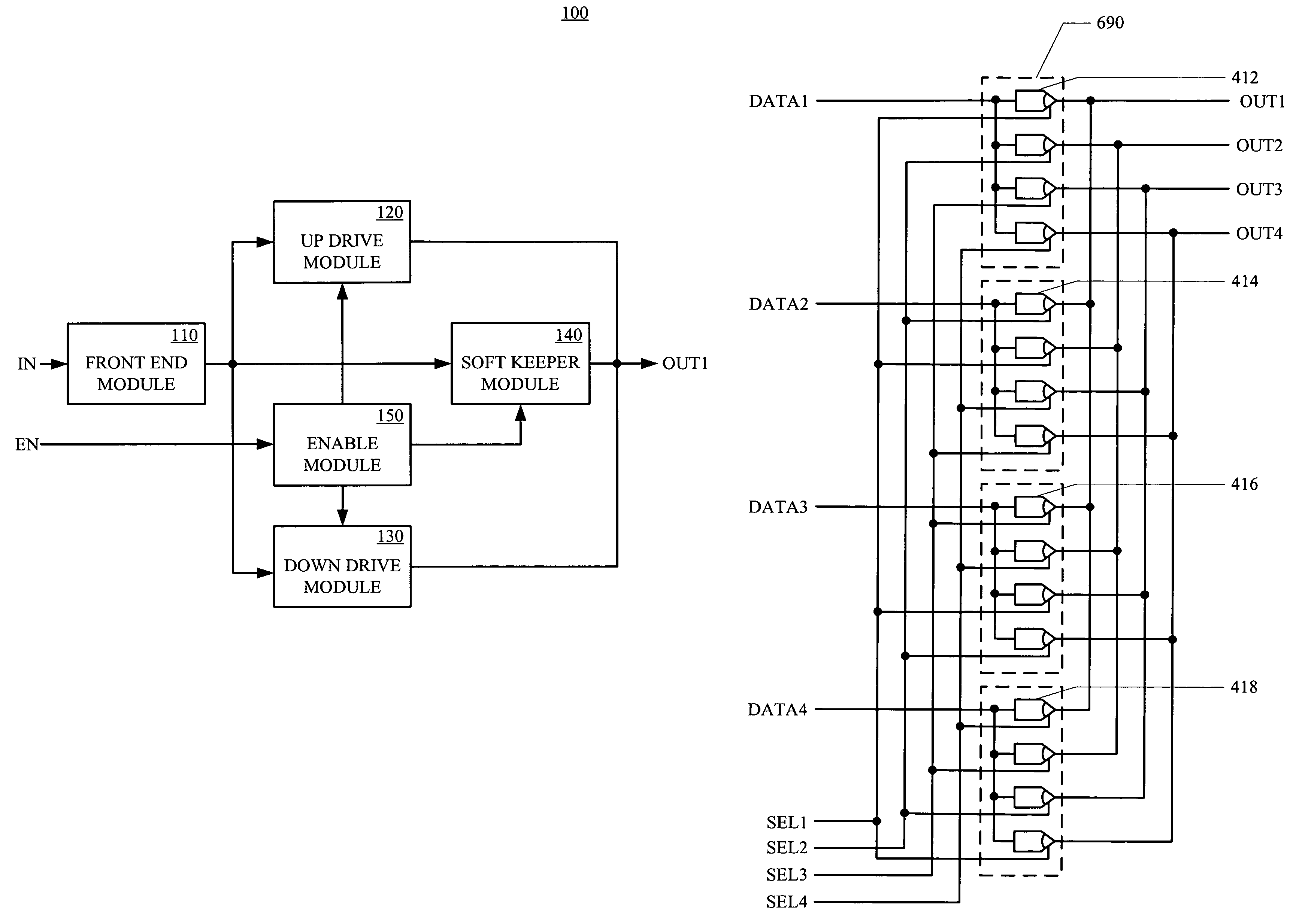
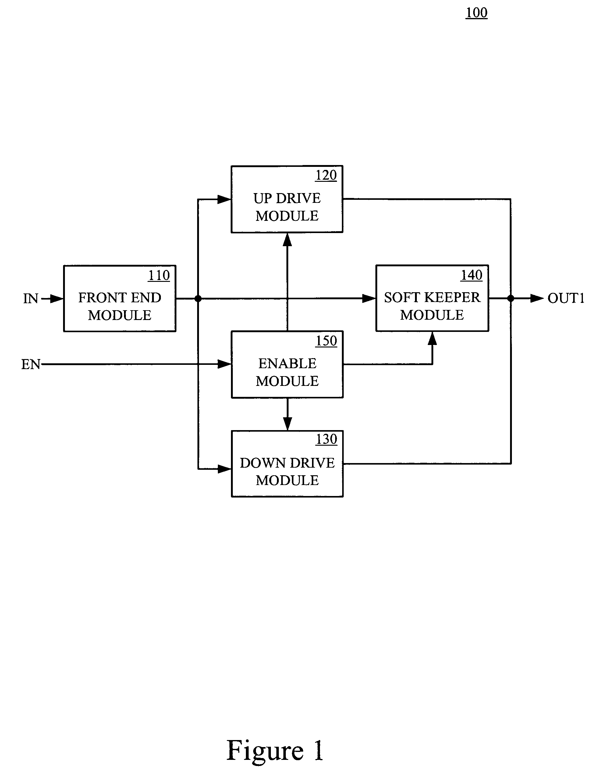
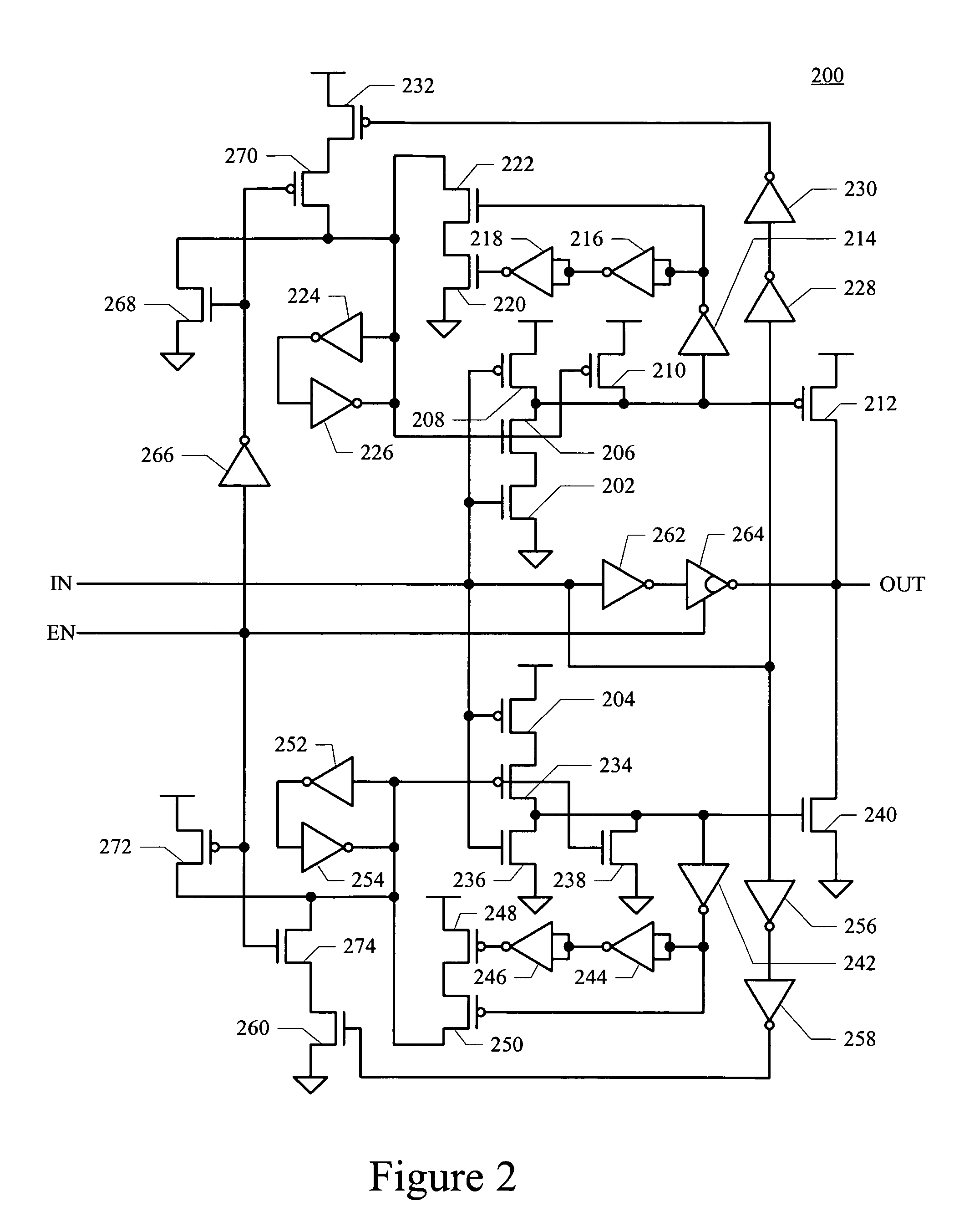
[0002]Embodiments of the present invention are directed toward a cross point switch that includes a plurality of tri-state repeaters coupled to form a plurality of multiplexers. Each set of corresponding tri-state repeaters in the plurality of multiplexers share a front end module such that delay through the cross point switch due to input capacitance is reduced as compared to conventional cross point switches. Each tri-state repeater includes an up drive module for generating a hard first drive state, a down drive module for generating a hard second drive state and a keeper module for generating a weak first drive state and a weak second drive state. The tri-state repeater further includes an enable module, wherein the output of the tri-state repeater operates in one of four states that includes the hard first drive state, the weak first drive state, the hard second drive state and the weak second drive state when a corresponding select signal is in a first enable state. Furthermore, the output operates in a moderate or high impedance state when the corresponding select signal is in a second enable state

Problems solved by technology

Propagation delay and distortion are some of the negative effects experienced by the signals propagating along the long metal wires.
However, in some IC chip designs, the maximum reduction in the RC constant is not sufficient to meet the design specifications.
However, conventional repeaters introduce a propagation delay as a result of one or more parasitic capacitances.

Method used


Image

  • Cross point switch
  • Cross point switch
  • Cross point switch

Examples


Embodiment Construction

[0012]Reference will now be made in detail to the embodiments of the invention, examples of which are illustrated in the accompanying drawings. While the invention will be described in conjunction with these embodiments, it will be understood that they are not intended to limit the invention to these embodiments. On the contrary, the invention is intended to cover alternatives, modifications and equivalents, which may be included within the scope of the invention as defined by the appended claims. Furthermore, in the following detailed description of the present invention, numerous specific details are set forth in order to provide a thorough understanding of the present invention. However, it is understood that the present invention may be practiced without these specific details. In other instances, well-known methods, procedures, components, and circuits have not been described in detail as not to unnecessarily obscure aspects of the present invention.

[0013]Referring to FIG. 1, a...


PUM


Abstract

A cross point switch, in accordance with one embodiment of the present invention, includes a plurality of tri-state repeaters coupled to form a plurality of multiplexers. Each set of corresponding tri-state repeaters in the plurality of multiplexers share a front end module such that delay through the cross point switch due to input capacitance is reduced as compared to conventional cross point switches.

Description

BACKGROUND OF THE INVENTION[0001]In integrated circuit (IC) chip designs, signals (e.g., clock signals, logic signals, power signals, etc.) may propagate along “long” metal wires in comparison to minimum design sizes available in the fabrication process utilized. Propagation delay and distortion are some of the negative effects experienced by the signals propagating along the long metal wires. These negative effects can be minimized by reducing the RC constant of the metal wire. However, in some IC chip designs, the maximum reduction in the RC constant is not sufficient to meet the design specifications. Thus, other techniques are used. One approach involves inserting repeater circuits at periodic intervals along the long metal wires in order to amplify (or remove distortion) the signals as well as to reduce propagation delay (or maintain fast transition times). However, conventional repeaters introduce a propagation delay as a result of one or more parasitic capacitances.SUMMARY OF...

Claims


Application Information

Patent Timeline
Patent Type & Authority Patents(United States)
IPC IPC(8): H03K19/094
CPCH03K17/002H03K19/09429
Inventor MASLEID, ROBERT P.PITKETHLY, SCOTT
Owner INTELLECTUAL VENTURES HOLDING 81 LLC
Why Eureka
Try Eureka