Lithographic apparatus and device manufacturing method

a technology of lithographic apparatus and manufacturing method, which is applied in the direction of photomechanical apparatus, instruments, optical instruments, etc., can solve the problems of reducing the efficiency of lithographic equipment, affecting the image quality of objects of different heights on the substrate table, and deleting disturbance forces to the substrate and/or projection system, etc., to achieve the effect of reducing or minimizing the barrier member and the substrate, reducing or minimizing the disturbance force, and improving the quality of lithographic imag

Inactive Publication Date: 2010-05-04
ASML NETHERLANDS BV
View PDF177 Cites 6 Cited by
  • Summary
  • Abstract
  • Description
  • Claims
  • Application Information

AI Technical Summary

Benefits of technology

[0018]In this way, in use, the immersion liquid is allowed to leak out of the space between the bottom of the barrier member and the substrate and is thereby not constrained in the space. Thus, the transmission of disturbance forces between the projection system, the barrier member and the substrate may be reduced or minimized. Furthermore, a high rate of liquid replenishment in the space may be possible without the necessity for the use of high liquid pressures. The force in the direction of the optical axis on the substrate table may also be reduced and be more constant in comparison to other liquid supply systems. Also, unlike with other supply systems, the imaging of edge portions may become easier as complicated measures are not necessary as the barrier member passes over the edge of the substrate as there is no seal to be disturbed at the edge of the substrate. The simplicity of the barrier member may be increased as only liquid inlets are required and no gas supplies. The lack of gas supplies means that the chance of bubble formation in the immersion liquid which can deleteriously affect the imaging quality may reduced or minimized. Finally, a larger free working distance (the distance between the projection system and the substrate) may be increased compared to other supply systems.
[0019]In an embodiment, the apparatus further comprises at least one outlet to remove immersion liquid, the outlet being radially outwardly of the barrier member. In this way immersion liquid which has spilled from the localized area of the supply system (i.e. the area under the projection system) may be collected without adding to the complexity of the barrier member and without substantially transferring disturbance forces to the substrate and / or substrate table. In one embodiment the outlet is on the substrate table.
[0020]In an embodiment, the barrier member is mechanically isolated from the projection system so that disturbance forces are not automatically transmitted to the projection system by the barrier member. In an embodiment, the barrier member is connected to a base frame which supports the substrate table and / or a projection system frame which supports the projection system. In an embodiment, the barrier member is free to move in the direction of an optical axis of the projection system.

Problems solved by technology

For example, the first solution has proved to be hard to implement without large and uncontrolled liquid spillage.
A further example is that the second and third solutions may deleteriously transmit disturbance forces to the substrate and / or projection system because of their close interaction with the surface of the substrate which is necessary in order to keep the liquid in the space.
Furthermore, each of the solutions may not be particularly well suited for imaging objects of different height on the substrate table, such as through lens sensors.
There is not a great deal of available space with these systems between the projection system and the substrate and building a liquid supply system which can operate at high NA can be difficult.
Each of the solutions may present difficulties with the imaging of edge portions of the substrate, such as the gas seal may become unbalanced when it is partly positioned over the edge of the substrate and / or the capillary force can be lost when imaging edge portions.

Method used


Image

  • Lithographic apparatus and device manufacturing method
  • Lithographic apparatus and device manufacturing method
  • Lithographic apparatus and device manufacturing method

Examples


Embodiment Construction

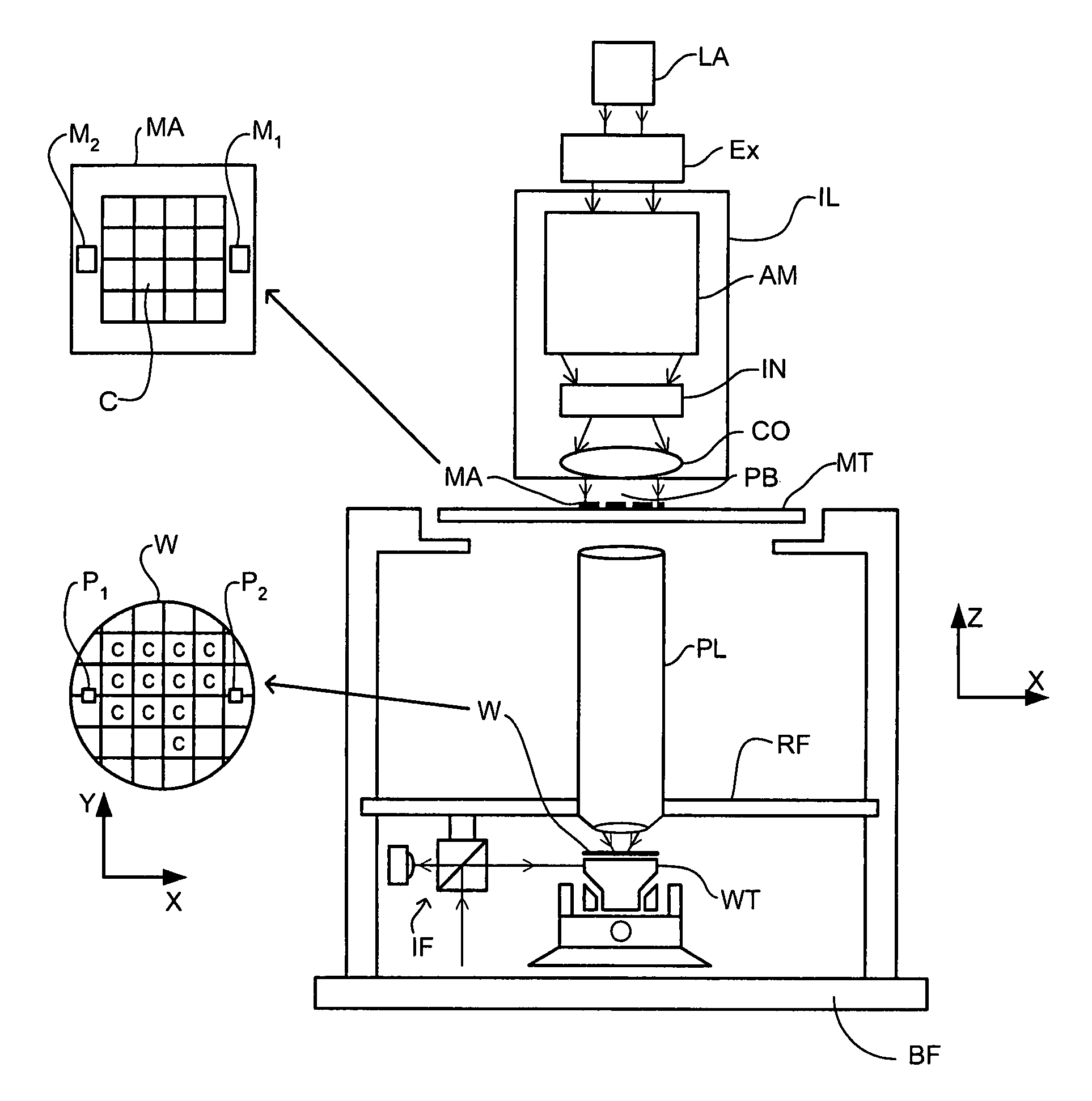
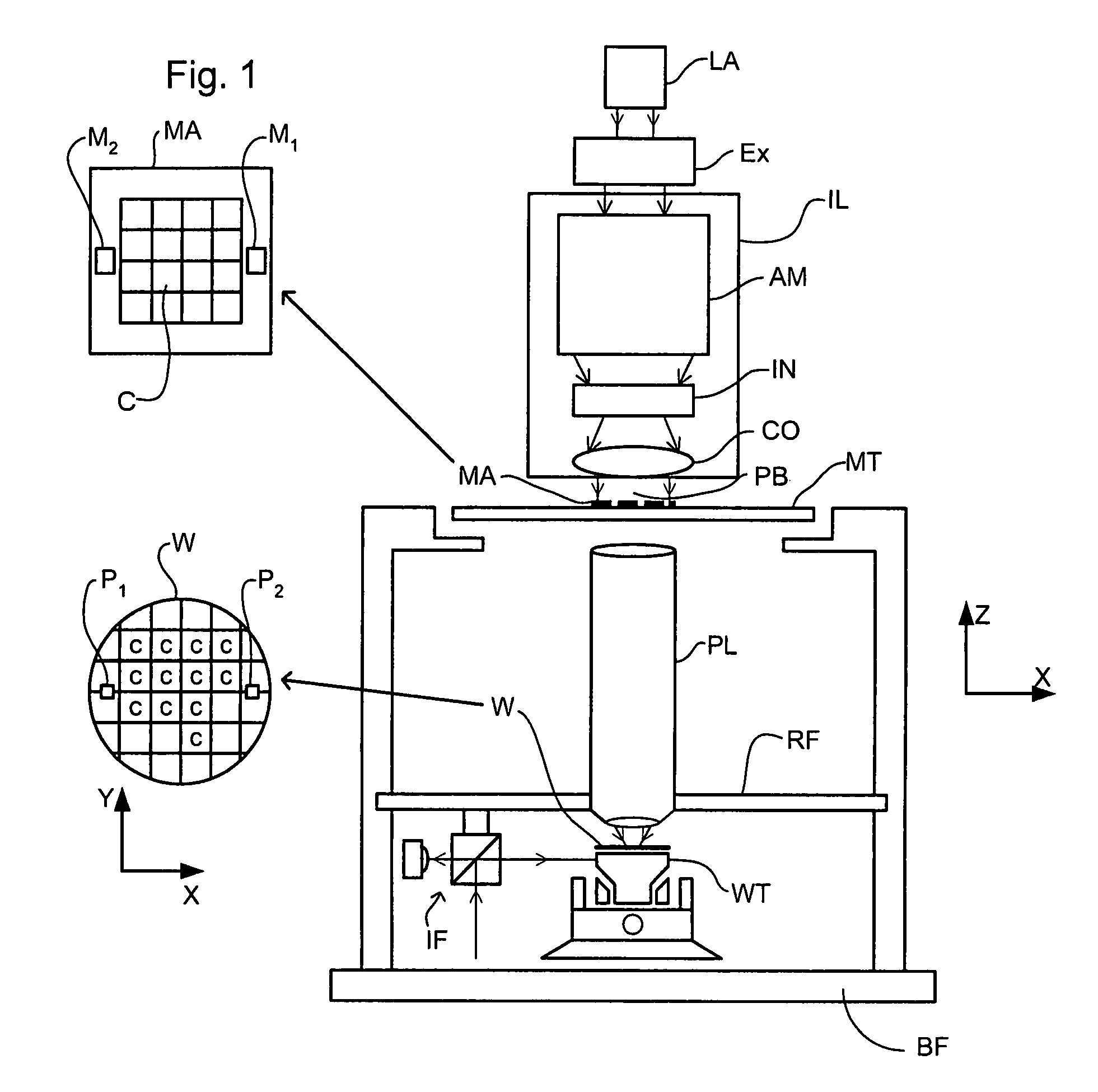
[0039]FIG. 1 schematically depicts a lithographic apparatus according to a particular embodiment of the invention. The apparatus comprises:[0040]an illumination system (illuminator) IL for providing a projection beam PB of radiation (e.g. UV radiation);[0041]a first support structure (e.g. a mask table) MT for supporting a patterning device (e.g. a mask) MA and connected to a first positioning device PM for accurately positioning the patterning device with respect to item PL;[0042]a substrate table (e.g. a wafer table) WT for holding a substrate (e.g. a resist-coated wafer) W and connected to a second positioning device PW for accurately positioning the substrate with respect to item PL; and[0043]a projection system (e.g. a refractive projection lens) PL for imaging a pattern imparted to the projection beam PB by patterning device MA onto a target portion C (e.g. comprising one or more dies) of the substrate W.

[0044]As here depicted, the apparatus is of a transmissive type (e.g. emp...


PUM

PropertyMeasurementUnit
wavelengthaaaaaaaaaa

Abstract

A liquid supply system for an immersion lithographic projection apparatus is disclosed in which a space is defined between the projection system, a barrier member and a substrate. The barrier member is not sealed such that, during use, immersion liquid is allowed to flow out the space and between the barrier member and the substrate.

Description

[0001]This application is a continuation of co-pending U.S. patent application Ser. No. 10 / 743,271 filed Dec. 23, 2003, the entire contents of which is hereby incorporated by reference.FIELD[0002]The present invention relates to a lithographic apparatus, a device manufacturing method and device manufactured thereby.BACKGROUND[0003]A lithographic apparatus is a machine that applies a desired pattern onto a target portion of a substrate. Lithographic apparatus can be used, for example, in the manufacture of integrated circuits (ICs). In that circumstance, a patterning device, such as a mask, may be used to generate a circuit pattern corresponding to an individual layer of the IC, and this pattern can be imaged onto a target portion (e.g. comprising part of, one or several dies) on a substrate (e.g. a silicon wafer) that has a layer of radiation-sensitive material (resist). In general, a single substrate will contain a network of adjacent target portions that are successively exposed. ...

Claims


Application Information

Patent Timeline
Patent Type & Authority Patents(United States)
IPC IPC(8): G03B27/42G03B27/52G03F7/20
CPCG03F7/70341G03F7/7085G03F7/20
Inventor VAN SANTEN, HELMARKOLESNYCHENKO, ALEKSEY
Owner ASML NETHERLANDS BV
Why Eureka
Try Eureka