Supercharge Your Innovation With Domain-Expert AI Agents!

Microactuator

a microactuator and actuator technology, applied in the field of microactuators, can solve the problems of difficult and costly manufacture of hinged devices, limited speed of polygon mirrors, and limited high-speed and large-displacement demands of microactuators, so as to reduce the mass of moving plates, increase resonance frequency, and high stiffness

Inactive Publication Date: 2010-05-04
SAMSUNG ELECTRONICS CO LTD
View PDF3 Cites 7 Cited by
  • Summary
  • Abstract
  • Description
  • Claims
  • Application Information

AI Technical Summary

Benefits of technology

The design effectively reduces the mass and stress of the moving plate, enhancing its resonance frequency and stiffness, enabling high-speed and large-displacement operations while maintaining light path reflection capabilities.

Problems solved by technology

However, since a spindle motor, which is required for driving most polygon mirrors, operates presently at a limited speed due to restrictions of oscillation, noise, and bearings, the speed of the polygon mirrors is limited to about 40,000 rpm (about 28 ppm) or lower.
It is difficult for the microactuators to meet both high-speed and large-displacement demands.
Also, since many components are used, the manufacture of the disclosed hinged device is difficult and costly.
Here, since a hinge portion has the same thickness as the entire structure, controlling a resonance frequency and induced stress is difficult to achieve.

Method used


Image

  • Microactuator
  • Microactuator
  • Microactuator

Examples


Embodiment Construction

[0021]Reference will now be made in detail to the present embodiments of the present invention, examples of which are illustrated in the accompanying drawings, wherein like reference numerals refer to the like elements throughout. The embodiments are described below in order to explain the present invention by referring to the figures.

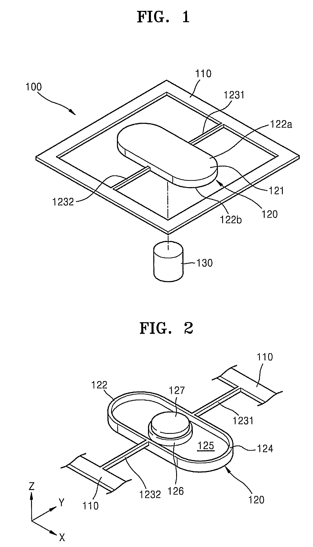
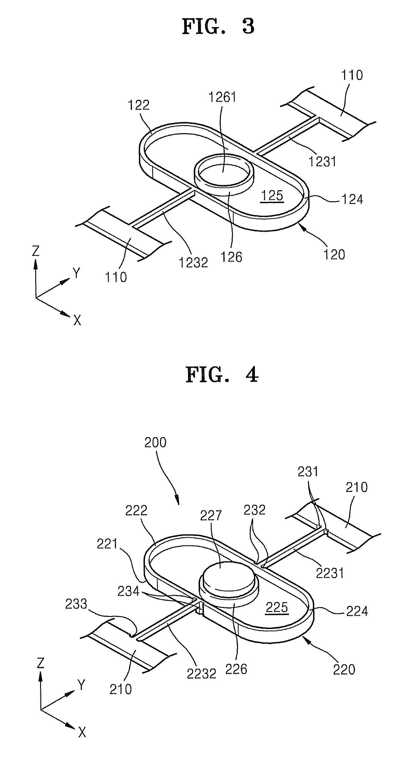
[0022]FIG. 1 is a perspective view of a microactuator 100 according to an embodiment of the present invention. FIG. 2 is a perspective view of a rear surface of the microactuator 100 shown in FIG. 1. FIG. 3 is a perspective view of the microactuator 100, shown in FIG. 2, from which a permanent magnet 127 has been removed.

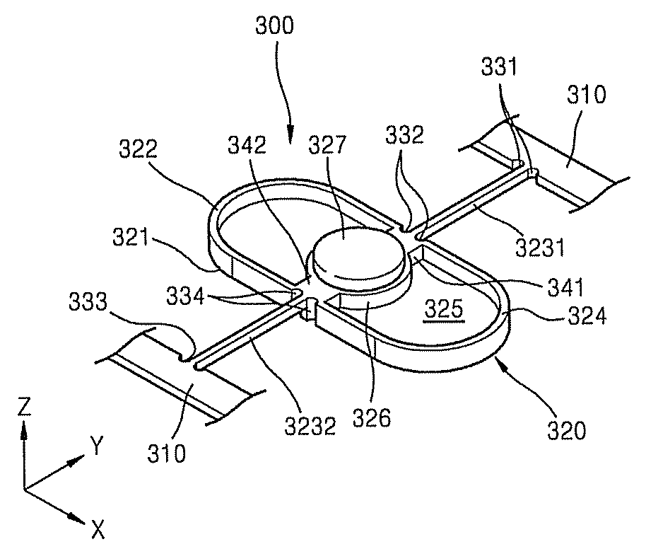
[0023]Referring to FIGS. 1 through 3, the microactuator 100 includes a base frame 110 and a moving plate 120 respectively supported by a plurality of elastic support portions 1231 and 1232 that are inside the base frame 110. According to other aspects of the invention, the microactuator 100 may include additional and / or different compo...


PUM


Abstract

A microactuator including a base frame; and a moving plate having both ends supported by a plurality of elastic support portions inside the base frame, the moving plate having a first side on which a reflective mirror for changing a light path is disposed. At least one first rib is disposed along an edge of a second side of the moving plate, which is the reverse side of the first side of the moving plate, and a second rib is disposed in the center of the second side of the moving plate and correspondingly encloses a permanent magnet. Also, a portion of the second side of the moving plate, except for the first and second ribs, is removed to a predetermined depth to reduce the weight of the entire moving plate and to define the first and second ribs.

Description

CROSS-REFERENCE TO RELATED APPLICATION[0001]This application claims the benefit of Korean Patent Application No. 2007-96941, filed in the Korean Intellectual Property Office on Sep. 21, 2007, the disclosure of which is incorporated herein by reference.BACKGROUND OF THE INVENTION[0002]1. Field of the Invention[0003]Aspects of the present invention relate to a microactuator, which reflects light to change a light path.[0004]2. Description of the Related Art[0005]In recent years, the development of printers and other image forming apparatuses has been oriented toward increasing printing speed. In order to design high-speed printers, it is necessary to accelerate the operations of a polygon mirror, since the operation of the polygon mirror significantly affect the printing speed of the printers. However, since a spindle motor, which is required for driving most polygon mirrors, operates presently at a limited speed due to restrictions of oscillation, noise, and bearings, the speed of th...

Claims


Application Information

Patent Timeline
Patent Type & Authority Patents(United States)
IPC IPC(8): G02B26/08
CPCG02B26/085G02B26/02G02B26/00
Inventor YOON, JIN-WOOKLEE, YONG-HOON
Owner SAMSUNG ELECTRONICS CO LTD
Features
  • R&D
  • Intellectual Property
  • Life Sciences
  • Materials
  • Tech Scout
  • Unparalleled Data Quality
  • Higher Quality Content
  • 60% Fewer Hallucinations
Learn More