
Method and system of real-time estimation of transmission line parameters in on-line power flow calculations

a technology of transmission line and power flow calculation, applied in the direction of measuring devices, instruments, cooling/ventilation/heating modification, etc., can solve the problem of insufficient “snapshot” off-line measurement of resistance and reactance parameters, insufficient on-line and real-time applications, and inability to measure the equivalent admittance of reactive charging power. to achieve the effect of improving the accuracy of state estimation

Active Publication Date: 2010-05-04
BRITISH COLUMBIA HYDRO & POWER AUTHORITY
View PDF4 Cites 19 Cited by
  • Summary
  • Abstract
  • Description
  • Claims
  • Application Information

AI Technical Summary

Benefits of technology

"The invention provides a method for real-time estimation of transmission line parameters for power system applications. The method uses synchronized phasor measurement units (PMUs) and filters out invalid measurements to improve accuracy. The method can be used in real-time applications and can be applied to various power system control centers. It is based on the fact that line parameters change with time and can be used to enhance accuracy of state estimation and power flows. The method is fast and reliable, and can be used in real-time monitoring of power systems."

Problems solved by technology

However, there is a difference between the calculated and actual parameters.
However, the equivalent admittance representing reactive charging power is not measurable.
Also, a “snapshot” off-line measurement of resistance and reactance parameters is not sufficient for on-line and real time applications, because in a real live environment, resistance, reactance and equivalent admittance of lines vary with environment and weather (such as temperature and wind speed).
Therefore, the assumption of constant parameters may create unacceptable error, particularly when the environment or weather around the line has a relatively large change.
All of the above methods are not designed for an application operating in real time or for on-line power flow modeling and calculations, and also cannot provide an estimation of equivalent admittance representing reactive charging power of a transmission line.

Method used


Image

  • Method and system of real-time estimation of transmission line parameters in on-line power flow calculations
  • Method and system of real-time estimation of transmission line parameters in on-line power flow calculations
  • Method and system of real-time estimation of transmission line parameters in on-line power flow calculations

Examples


Embodiment Construction

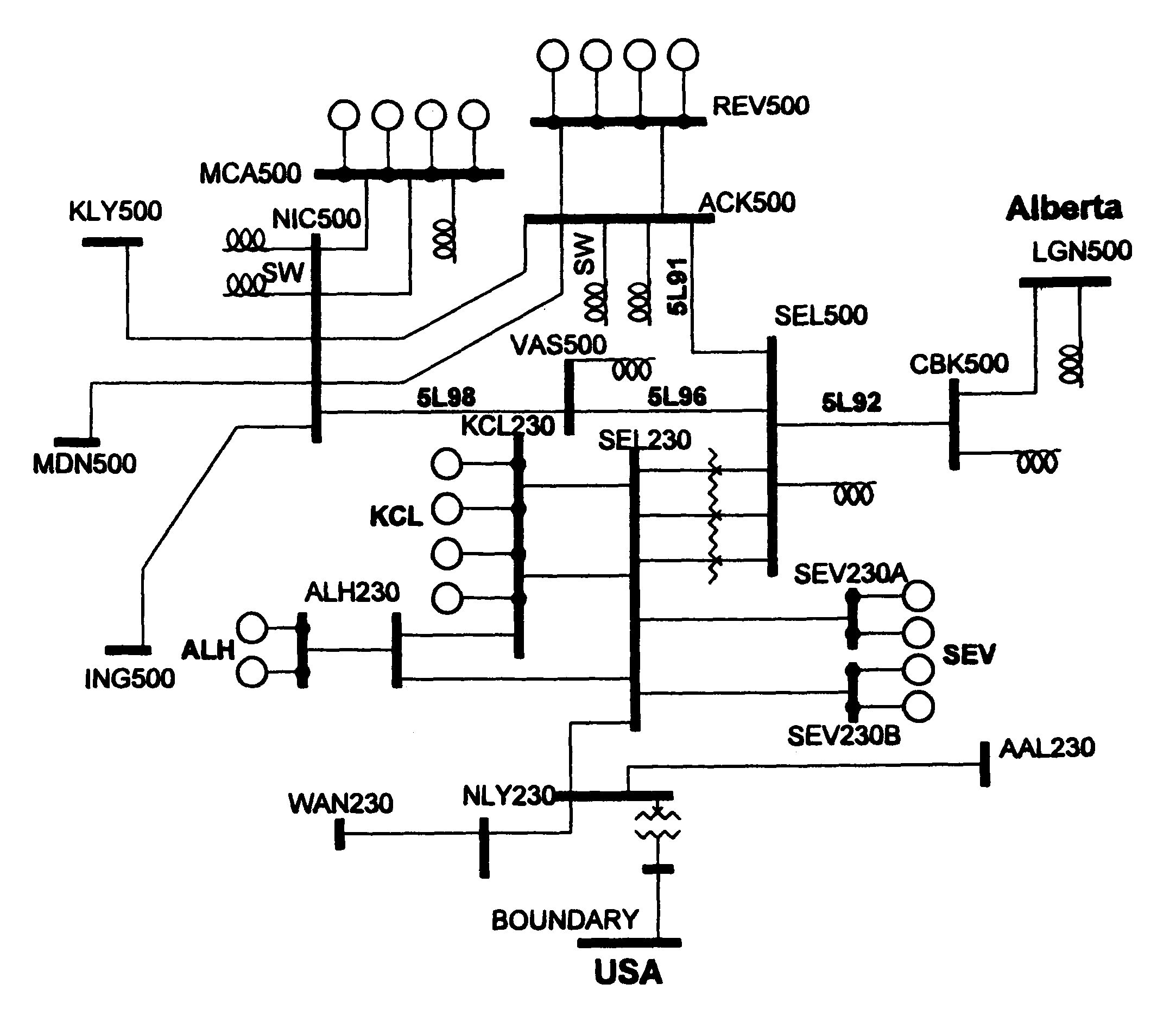
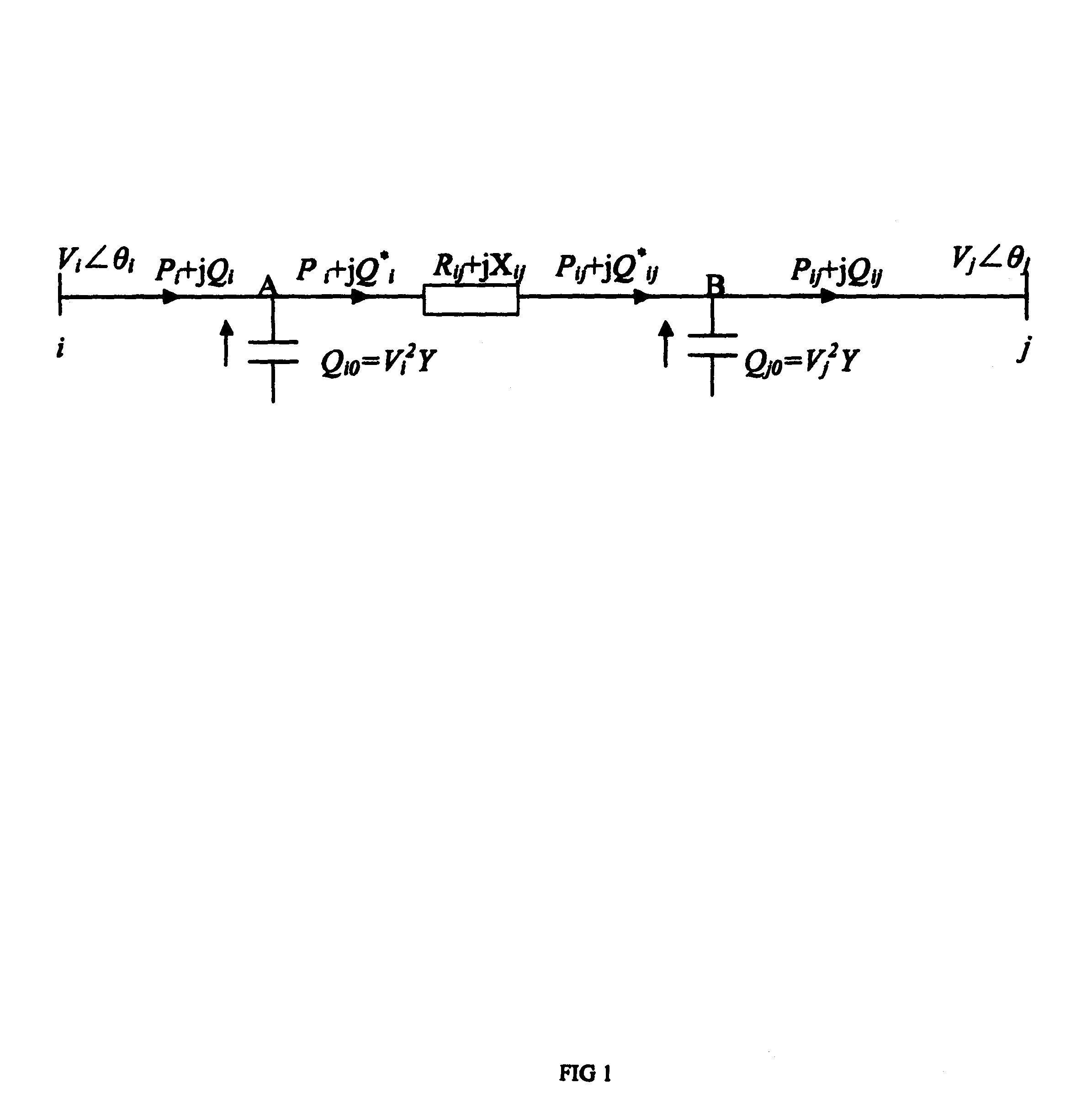
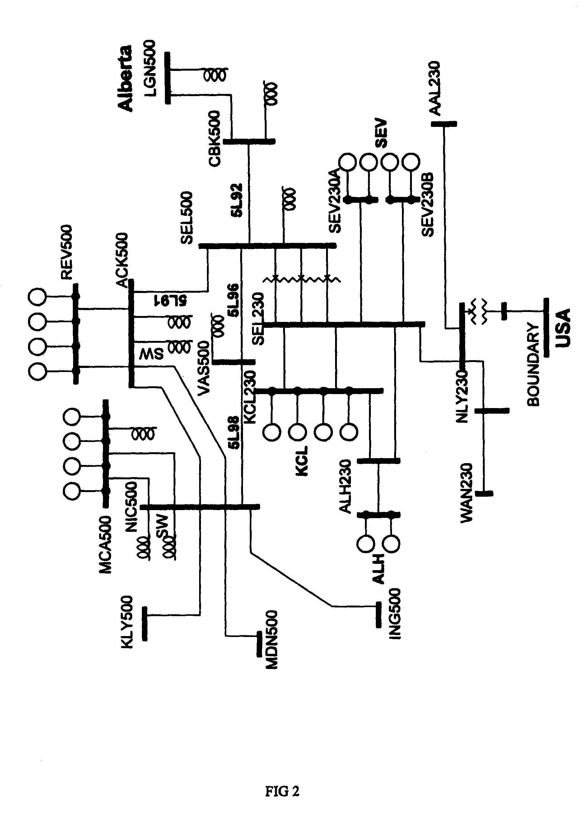
[0040]PMU devices are installed at two sides of a transmission line of which its parameters are to be estimated. The estimation includes two tasks:[0041](1) A measurement from a PMU may be invalid data. False data that is caused by failure or malfunction of PMUs or communication channels may or may not be recognized using features of PMU measurements. In particular, some errors that are only associated with accuracy of measurements cannot be identified by the PMU itself. Fortunately, the measured voltage and power flow phasors of a line must satisfy the relationship of line flow equation. This fact enables users to identify and filter out invalid measurements.[0042](2) The line (branch) parameters (i.e. resistance, reactance of lines and admittance representing reactive charging power) cannot be directly measured by a PMU. These parameters vary with environment and weather (such as temperature) conditions. Therefore it is necessary to perform a real time continuous estimation of lin...


PUM


Abstract

A system and method for estimating parameters of transmission lines employing phasor measurement units is provided, wherein measurements are provided from the phasor measurement units relating to a transmission line. These measurements are filtered to remove invalid measurements. Using the remaining valid measurements, resistance, reactance and grounding admittance are calculated and estimated and checked for errors.

Description

CROSS REFERENCE TO RELATED APPLICATIONS[0001]This application is related to the following:[0002]This application claims the benefit of Canadian Patent Application No. 2602888, filed Sep. 18, 2007, and claims priority of U.S. Provisional Patent Application No. 60 / 952,494, filed Jul. 27, 2007 which is hereby incorporated by reference.FIELD OF THE INVENTION[0003]This invention relates to methods of estimating transmission line parameters in power systems and more particularly to methods of using such estimations in real time power flow calculations.BACKGROUND OF THE INVENTION[0004]High voltage transmission line parameters include resistance, reactance, and equivalent admittance which represent reactive charging power along the line. These parameters are a necessary and important input in power system modeling, power flow computations, voltage stability assessment, line protection design and other applications. In the prior art, the transmission line parameters are calculated using theo...

Claims


Application Information

Patent Timeline
Patent Type & Authority Patents(United States)
IPC IPC(8): H05K7/20
CPCG01R27/16
Inventor LI, WENYUANCHOUDHURY, PAULSUN, JUN
Owner BRITISH COLUMBIA HYDRO & POWER AUTHORITY
Learn More