
Roofing assembly including sheet panels having side edge portions with projections mating with grooves on brackets anchored to roof

a technology of sheet metal and assembly, applied in the field of building, can solve the problems of requiring the use of particular tools, requiring a somewhat laborious assembly process, and requiring the performance of complex operations, etc., and achieve the effect of high visual uniformity

Active Publication Date: 2010-05-11
ISCOM SPA
View PDF16 Cites 13 Cited by
  • Summary
  • Abstract
  • Description
  • Claims
  • Application Information

AI Technical Summary

Benefits of technology

[0013]The object of this invention is to overcome the above drawbacks, by providing a modular roofing assembly that is highly efficient and relatively cost-effective.
[0014]A particular object is to provide a roofing assembly that has high stability and resistance even when subjected to stresses acting substantially transverse to the extension of the assembly.
[0015]Another particular object of the invention is to provide a roofing assembly that can be easily assembled and dismantled.

Problems solved by technology

As is apparent, these conventional solutions have the drawback of requiring a somewhat laborious assembly process, and of requiring the performance of complex operations, using particular tools.
Furthermore, the anchorage holes in the sheets are weak points, possibly giving rise to cracks or metal weakening areas, as well as permeable points for the whole structure.
Therefore, these structures are excessively vulnerable to weather conditions, particularly rain, in case of possibly imperfect connections, and wind, especially in cantilever roofing assemblies.
While these arrangements provide an easy-to-mount covering assembly, having excellent characteristics of load and weather resistance and impermeability, it still has a few drawbacks and is susceptible to improvements.

Method used


Image

  • Roofing assembly including sheet panels having side edge portions with projections mating with grooves on brackets anchored to roof
  • Roofing assembly including sheet panels having side edge portions with projections mating with grooves on brackets anchored to roof
  • Roofing assembly including sheet panels having side edge portions with projections mating with grooves on brackets anchored to roof

Examples


Embodiment Construction

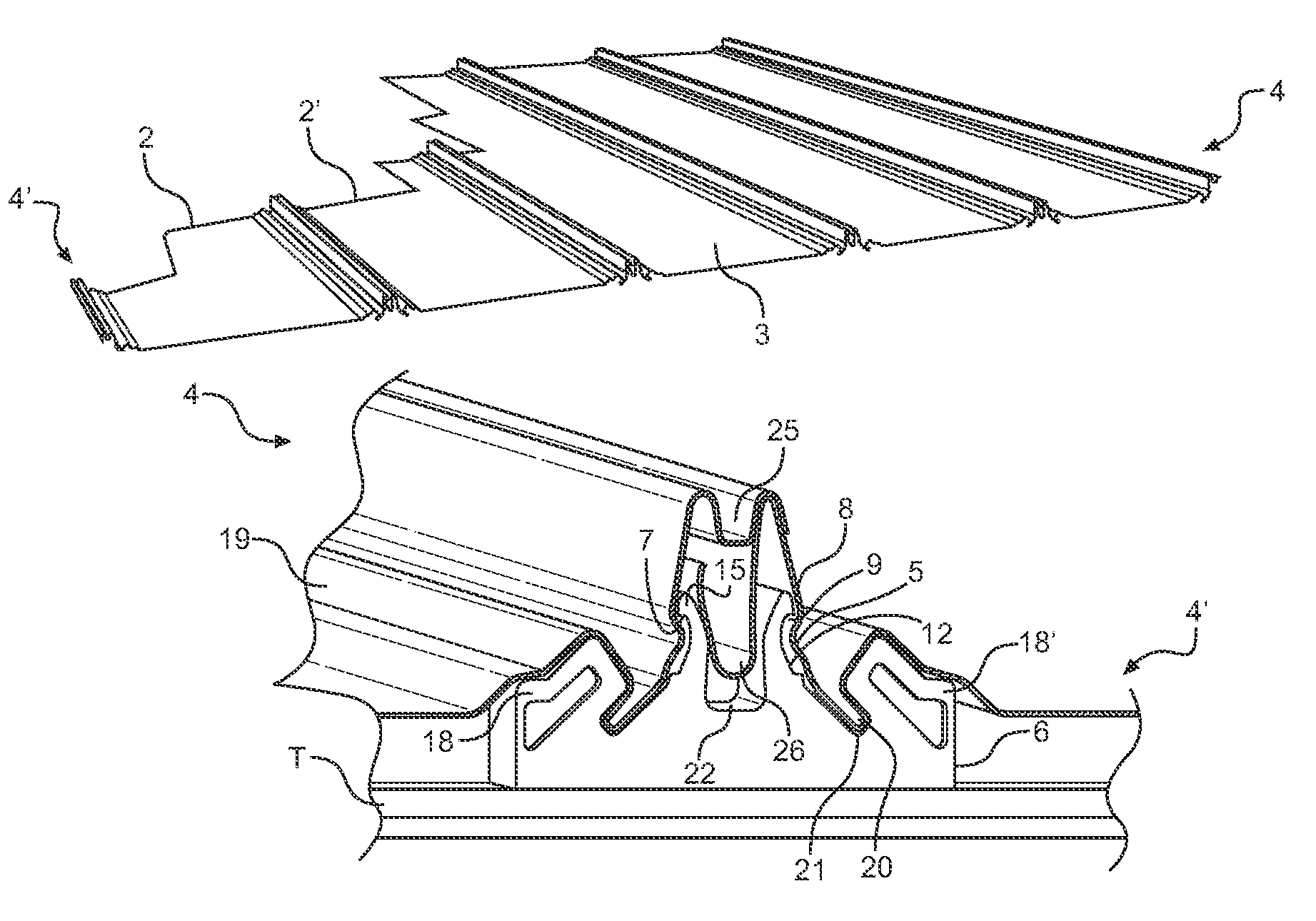
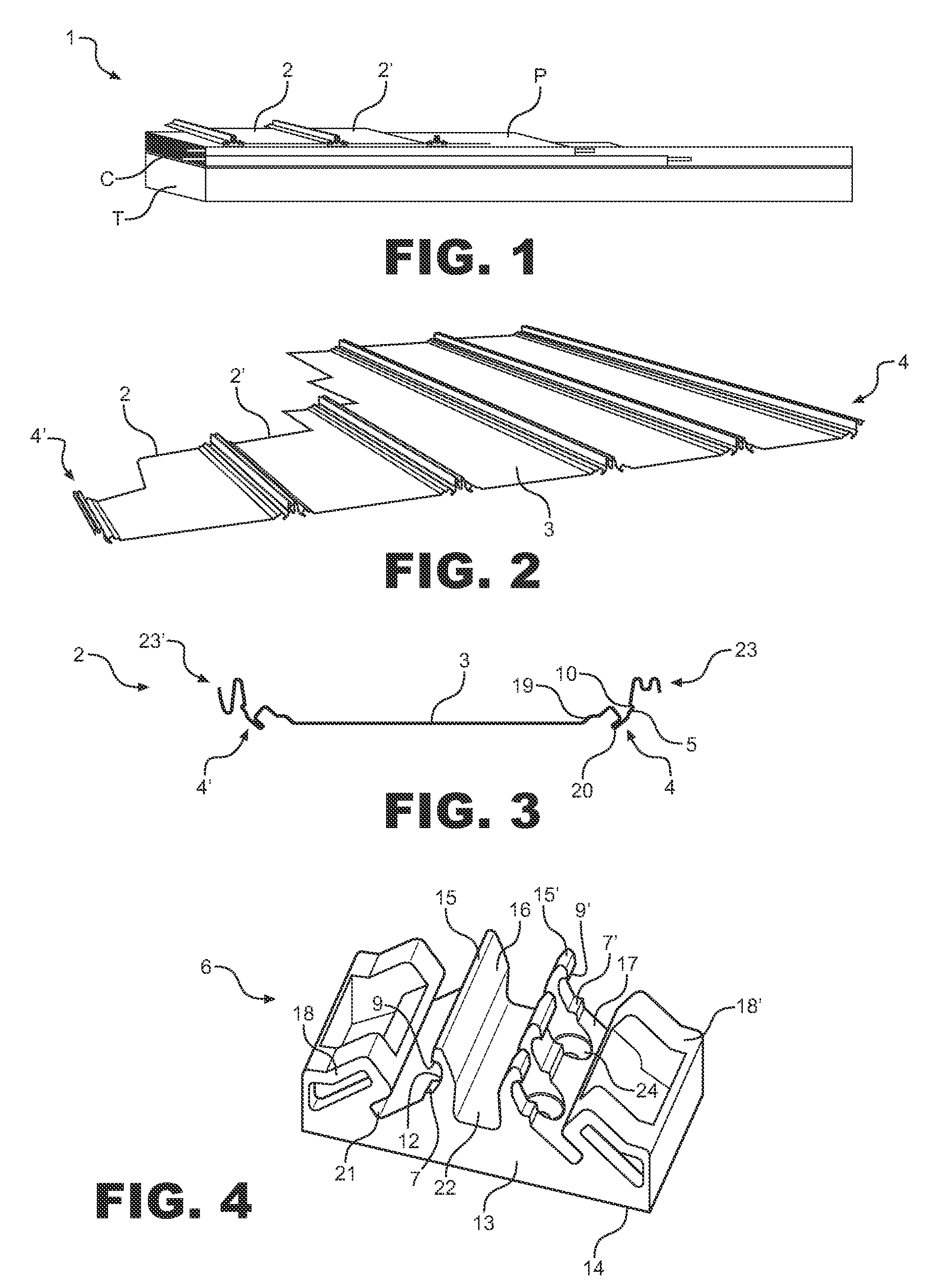
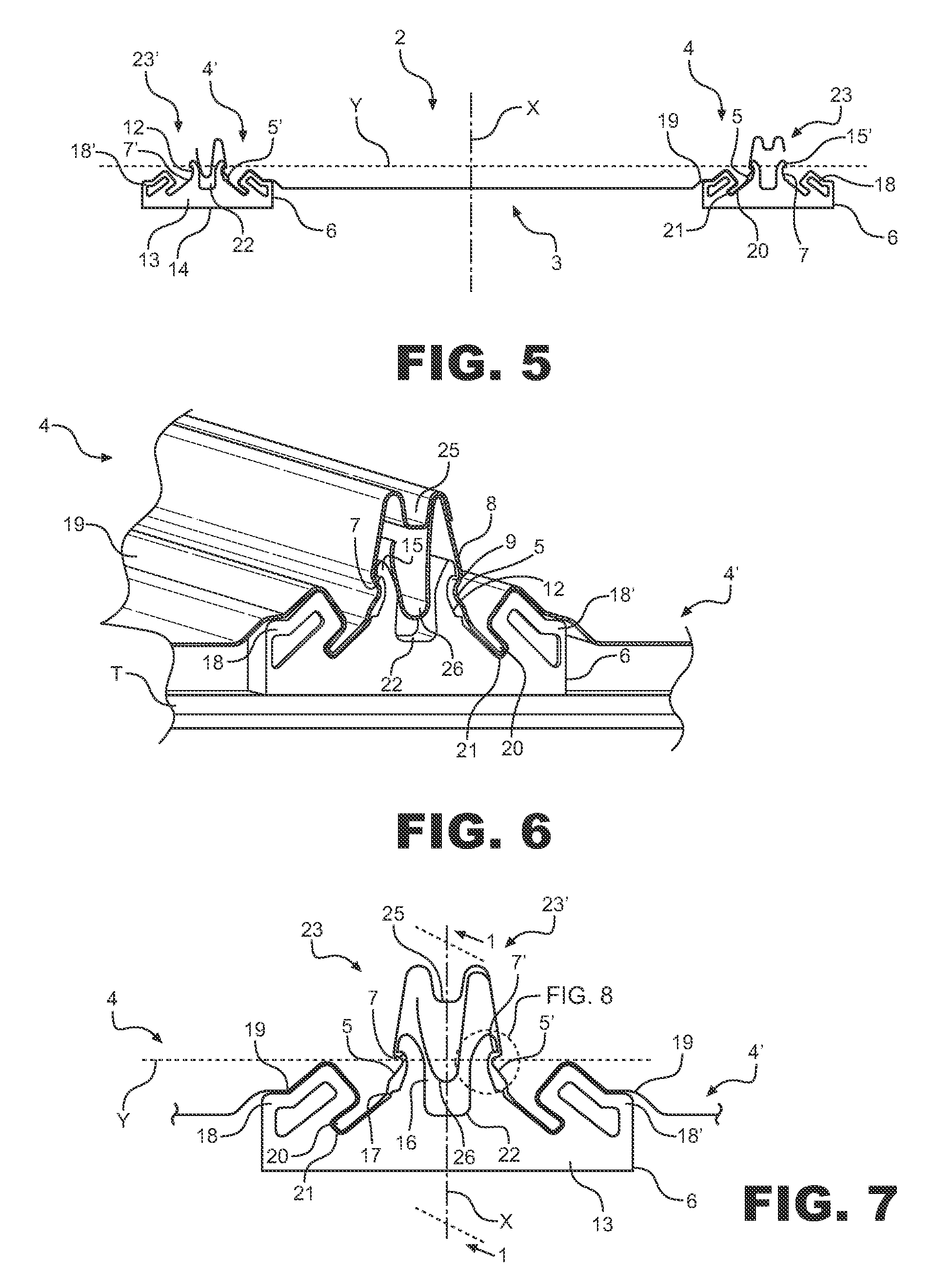
[0045]Referring to the above figures, the assembly of the invention, generally designated with numeral 1, may provide, as shown in the figures, a roofing assembly having high resistance, particularly suitable for use with roofs of residential and industrial buildings.

[0046]As particularly shown in FIG. 1, the assembly is composed of a plurality of modular sheet panels 2, disposed in adjacent positions to form a roofing system for a roof T. The anchorage of these panels to the load bearing structure is carried out by using a plurality of anchor brackets 6, which may be connected to the purlin or any other support of the roof T. The structure of the latter may include one or more intermediate insulation panels P under the sheet panels 2 and service channels may be provided between the building structure and the panels 2.

[0047]As shown in FIGS. 2 and 3, the sheet panels 2 have a substantially flat central portion 3, and two substantially parallel side edge portions 4, 4′. The panels ar...


PUM


Abstract

A roofing structure for buildings, and more particularly a roofing assembly having high resistance, especially for use with roofs of residential and industrial buildings. The assembly comprises a plurality of sheet panels to be interconnected along side edge portions shaped to define a first longitudinal projection facing laterally outwards, and multiple mounting brackets to be anchored to a roof. Each bracket has at least one longitudinal groove to house in a snap fit relationship the first longitudinal projections of adjacent panels, so that the first longitudinal projections and the groove have opposing upper surfaces at least partly flat and substantially parallel or slightly inclined, in order to enhance the retaining action of the brackets and increase the separation load causing the separation of the edge portions from the brackets.

Description

FIELD OF THE INVENTION[0001]The present invention finds application in the field of building and, more particularly, relates to a roofing assembly having high resistance, suitable for use with roofs of residential and industrial buildings.BACKGROUND OF THE INVENTION[0002]Modular roofing assemblies are increasingly applied for the protection of buildings or other load-bearing structures, for both residential and industrial use, which assemblies are made of metal sheets having specially profiled edges, and are either pre-assembled or directly mounted to the roofing.[0003]These particular roofing systems have a much lighter weight than conventional solutions, and further assure enhanced universal use.[0004]The connection to the load-bearing structure of the roof is usually obtained by directly attaching the metal sheets to the structure, typically by perforation and / or punching. Furthermore, these sheets are interconnected by placing adjacent sheets in such a manner to provide an overl...

Claims


Application Information

Patent Timeline
Patent Type & Authority Patents(United States)
IPC IPC(8): E04D1/34
CPCE04D3/30E04D3/363E04D2003/3612
Inventor LONARDI, GIORGIO
Owner ISCOM SPA
Learn More