
Liquid state detecting sensor

a liquid state and sensor technology, applied in liquid/fluent solid measurement, instruments, machines/engines, etc., can solve the problems that the reduction of nitrogen oxides cannot be satisfactorily achieved, and achieve the effect of speeding up the detection of the state, reducing the time and trouble involved in providing the mounting portions, and reducing the volume of the sensor occupying the interior of the accommodating container

Inactive Publication Date: 2010-05-11
NGK SPARK PLUG CO LTD
View PDF11 Cites 6 Cited by
  • Summary
  • Abstract
  • Description
  • Claims
  • Application Information

AI Technical Summary

Benefits of technology

The present invention relates to a liquid state detecting sensor for detecting the level and concentration of a liquid in a container. The sensor uses an electrostatic capacity-type sensor that measures the electrostatic capacity between two electrodes. The sensor can detect the level of the liquid and the concentration of the liquid using a single sensor. This eliminates the need for separate sensors for level and concentration detection and allows for the increased volume of the liquid in the container without enlarging the size of the sensor. The sensor also prevents freezing of the liquid when the temperature is low. The technical effect of the invention is to provide a more efficient and effective solution for detecting the level and concentration of a liquid in a container.

Problems solved by technology

For this reason, even if the residual quantity of the urea aqueous solution is a proper quantity, there is a possibility that the reduction of the nitrogen oxides cannot be effected satisfactorily in cases where the concentration of the urea aqueous solution has deviated from a proper range due to such as a change over time and in cases where a liquid (light oil, water) other than the proper urea aqueous solution is accommodated in a urea water tank.

Method used


Image

  • Liquid state detecting sensor
  • Liquid state detecting sensor
  • Liquid state detecting sensor

Examples


Embodiment Construction

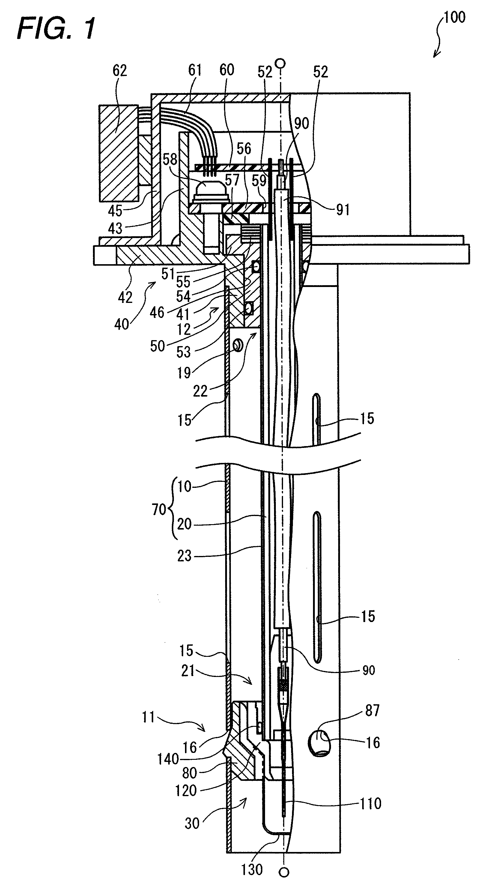
[0079]Hereafter, referring to the drawings, a description will be given of one mode of carrying out the liquid state detecting sensor embodying the invention. Referring to FIGS. 1 to 10, a description will be given of the structure of a liquid state detecting sensor 100 as one example.

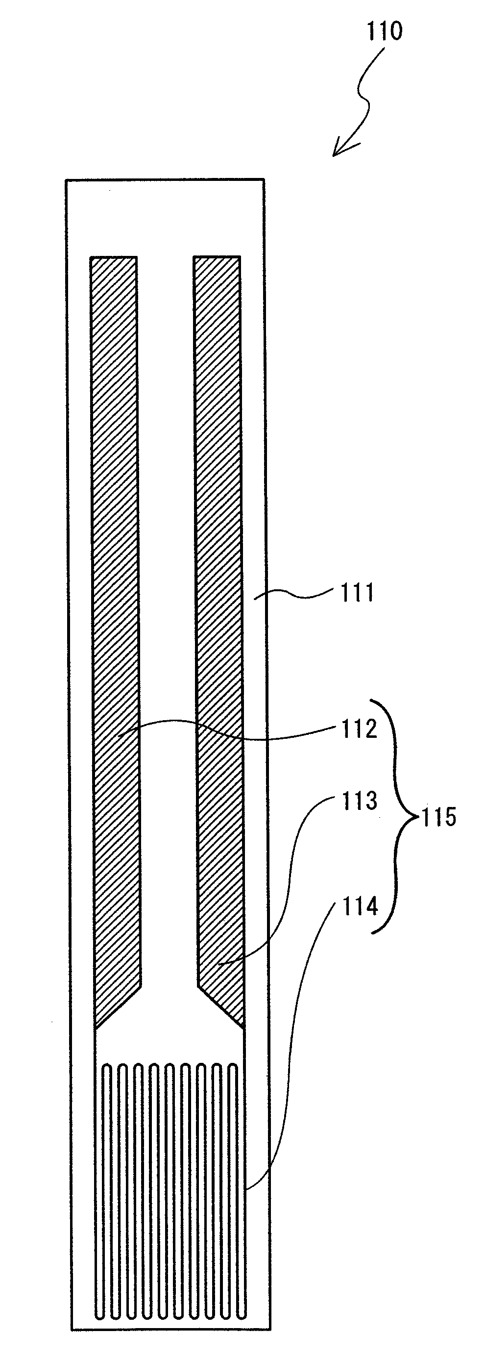
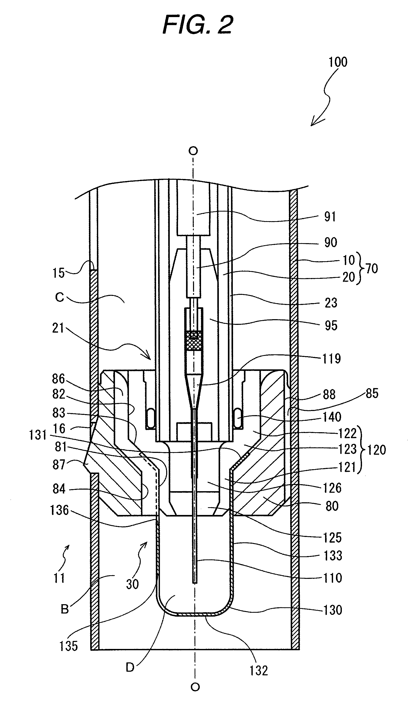
[0080]FIG. 1 is a fragmentary longitudinal cross-sectional view of the liquid state detecting sensor 100. FIG. 2 is an enlarged cross-sectional view of a liquid property detecting unit 30 and its vicinities of the liquid state detecting sensor 100. FIG. 3 is a schematic diagram illustrating a heater pattern 115 of a ceramic heater 110. FIG. 4 is a side elevational view of a protector 130. FIG. 5 is a bottom view of the protector 130. FIG. 6 is a perspective view in which a rubber bushing 80 is viewed from obliquely below. FIG. 7 is a side elevational view of the rubber bushing 80. FIG. 8 is a plan view of the rubber bushing 80. FIG. 9 is a cross-sectional view of the rubber bushing 80 taken in the dire...


PUM


Abstract

A liquid state detecting sensor is provided in which a level detecting unit for detecting the level of a liquid and a concentration detecting unit for detecting the concentration of a particular component contained in the liquid are integrated.In a liquid state detecting sensor 100 capable of measuring the level and a urea concentration of a urea aqueous solution, a level detecting unit 70 and a liquid property detecting unit 30 are connected in an insulated state. An outer cylinder electrode 10 and an inner electrode 20 for forming the level detecting unit 70 form a capacitor, and level detection is performed on the basis of the electrostatic capacity which changes in response to the level of the urea aqueous solution which is present therebetween. A holder 120 for holding a ceramic heater 110 is fitted to a leading end portion 21 of the inner electrode 20, and the holder 120 is supported inside a leading end portion 11 of the outer cylinder electrode 10 by a rubber bushing 80. Further, the urea concentration is determined by a liquid property detecting circuit unit of a circuit board 60 by energizing a heat generating resistor pattern provided on the ceramic heater 110 for a fixed time duration and on the basis of a voltage value corresponding to a resistance value of the heat generating resistor pattern obtained at this time.

Description

TECHNICAL FIELD[0001]The present invention relates to a liquid state detecting sensor for detecting the level of a liquid accommodated in a liquid accommodating container and at least the concentration of a particular component contained in the liquid.BACKGROUND ART[0002]Conventionally, a level sensor for detecting, for instance, the level (liquid level) of a liquid is known as an example of a sensor for detecting the state of a liquid, an electrostatic capacity-type liquid meter as its example is used in the measurement of the residual quantity of fuel in an automobile, for example (e.g., refer to patent document 1). In this electrostatic capacity-type liquid meter, a capacitor is formed between an elongated tubular electrode (outer cylinder electrode) made of a conductor and a tubular electrode (inner electrode) provided within that tube along the axial direction (hereafter referred to as the “gap”) so as to measure its electrostatic capacity. The electrostatic capacity-type liqui...

Claims


Application Information

Patent Timeline
Patent Type & Authority Patents(United States)
IPC IPC(8): G01F23/00
CPCG01F23/268G01F23/266F01N3/206F01N2610/02F01N2610/14
Inventor SASANUMA, TAKEOSATO, YOSHIKUNIYAMAMOTO, TAKASHI
Owner NGK SPARK PLUG CO LTD
Learn More