
Method of brazing pipe member to counterpart member

a technology of brazing pipe and counterpart member, which is applied in the direction of soldering apparatus, manufacturing tools, light and heating equipment, etc., can solve the problems of time and trouble in production, requiring a high production cost, and the remaining metal is narrow, so as to save time and trouble at the time of manufacturing, and facilitate positioning. , the effect of saving time and troubl

Active Publication Date: 2011-07-05
USUI KOKUSAI SANGYO KAISHA LTD
View PDF17 Cites 1 Cited by
  • Summary
  • Abstract
  • Description
  • Claims
  • Application Information

AI Technical Summary

Benefits of technology

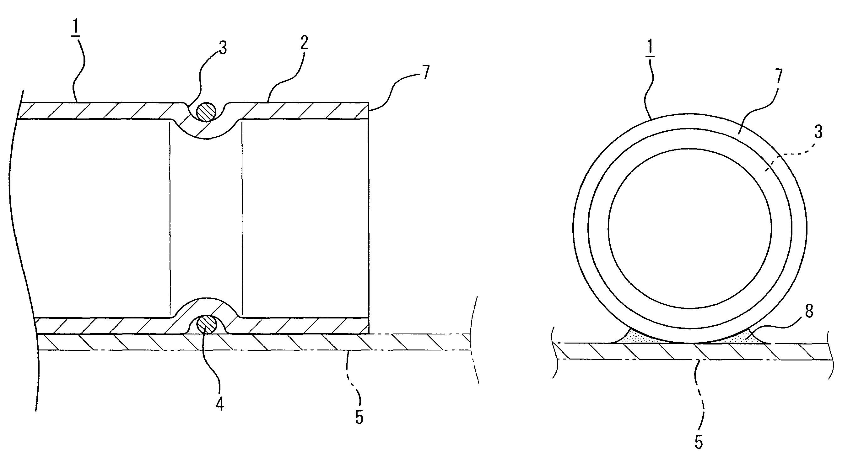
[0015]This invention is structured as described above. In the method of brazing the pipe member to the counterpart member according to this invention, the engaging portion in a ring shape is mounted in a circumferential direction to the outer periphery of the pipe end portion as the vicinity of the pipe endmost portion of the pipe member. The brazing-filler-metal-made ring in a ring shape is then provided to this engaging member in an engaging manner, so that the brazing-filler-metal-made ring can be easily positioned with respect to the pipe end portion. Furthermore, the brazing-filler-metal-made ring thus provided to the engaging portion is subjected to the heating and melting process to certainly braze only the abutment portion between the pipe member and the counterpart member. Thus, the pipe end portion and the counterpart member can be secured by brazing at a low cost without wasting the brazing filler metal while the brazing at the predetermined position can be performed easily and certainly.
[0016]Furthermore, where a deep portion in the counterpart member or an interior of the counterpart member, which is a sealed container-like shape, is secured by brazing, it is difficult to view these brazed parts after the brazing in some cases. However, a user views a status that the brazing-filler-metal-made ring is provided to the vicinity of the pipe endmost portion in an engaging manner when incorporating the pipe member into the counterpart member, thereby eliminating the need for checking the brazed parts even in the aforementioned cases, so that time and trouble at the time of manufacturing can be saved.

Problems solved by technology

In this manner, the metal covers unnecessary parts, thereby causing waste.
As a result, the production takes time and trouble while requiring a high production cost.
In this case, there has been a fear that the remaining metal narrows a flow channel for liquid or gas that flows through the connected part between the pipe member and the counterpart member.
In this case, it has been difficult to perform the brazing operation to the desired position with accuracy.

Method used


Image

  • Method of brazing pipe member to counterpart member
  • Method of brazing pipe member to counterpart member
  • Method of brazing pipe member to counterpart member

Examples


first embodiment

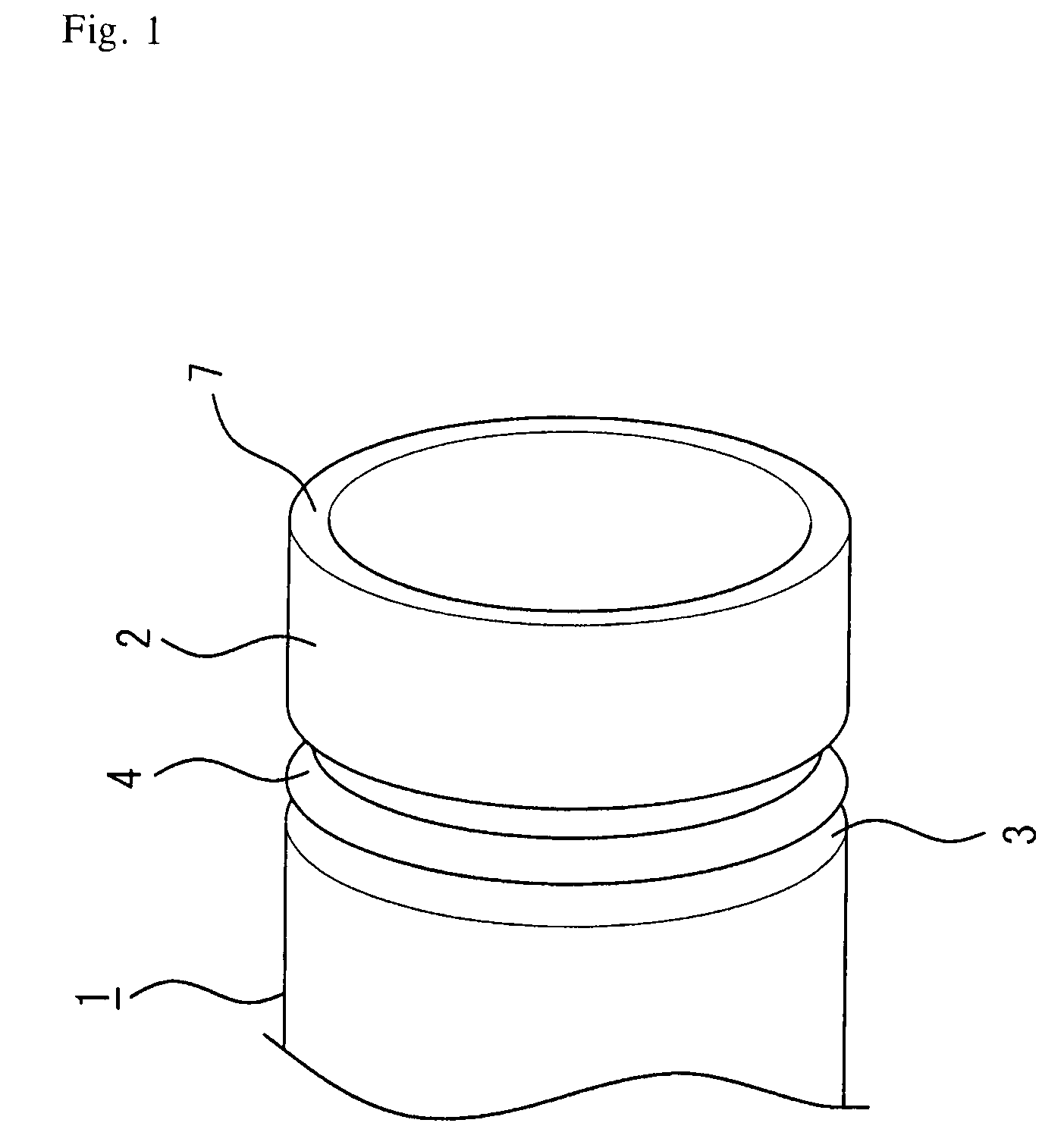
[0030]A first embodiment showing a first aspect of this invention will be explained with reference to FIGS. 1, 2, and 3. Numeral 1 is a pipe member in a cylindrical shape. An engaging portion 3 in a ring shape, which is inwardly formed in a concave manner, is mounted to an outer periphery of a pipe end portion 2 at one end of the pipe member 1 in a circumferential direction of the pipe member 1, as shown FIG. 1. Furthermore, independently from the pipe member, a brazing-filler-metal-made ring 4 is formed by shaping a wire-formed brazing filler metal into a ring shape in a manner to have an inner diameter set to smaller than an outer diameter of the pipe end portion 2.

[0031]The brazing-filler-metal-made ring 4 is elastically deformed to expand the diameter thereof to be slightly larger than an outer diameter of the pipe end portion 2. In this condition, the pipe member 1 is thrust into the brazing-filler-metal-made ring 4 to be inserted therein from a side of the pipe end portion 2 s...

second embodiment

[0034]In the first embodiment, the engaging portion 3 in a ring shape is formed in a concave manner to the pipe end portion 2 of the pipe member 1 in a cylindrical shape and the brazing-filler-metal-made ring 4 is provided to the engaging member 3, thereby brazing the pipe end portion 2 to the counterpart member 5. In a second embodiment of a second aspect of the invention, although the brazing-filler-metal-made ring 4 is provided to the engaging portion 3 of the pipe end portion 2 in the same manner as that of the first embodiment, the pipe end portion 2 provided with the brazing-filler-metal-made ring 4 is deformed in a manner to have a cross section in an oblong shape as a noncircular shape.

[0035]This embodiment will be explained with reference to FIGS. 4 and 5. The engaging portion 3 in a ring shape, which is similar to that of the first embodiment, is formed in a concave manner to the pipe end portion 2 of the pipe member 1 in a cylindrical shape. After providing the brazing-fi...

third embodiment

[0037]In the above first and second embodiments, the outer periphery of the pipe end portion 2 is mounted with the engaging portion 3 in a ring shape that is inwardly formed in a concave manner while the brazing-filler-metal-made ring 4 is provided to the engaging portion 3. In a third embodiment of a third aspect of the invention, however, the outer periphery of the pipe end portion 2 is mounted with the engaging portion 3 in a ring shape which is outwardly formed in a projecting manner, and the brazing-filler-metal-made ring 4 is provided to the engaging portion 3 in an engaging manner.

[0038]The third embodiment will be explained in more detail with reference to FIGS. 6 and 7. As shown in FIG. 6, the engaging portion 3 in a ring shape is formed in an outwardly projecting manner to the outer periphery of the pipe end portion 2 in a circumferential direction. The brazing-filler-metal-made ring 4 in a ring shape, which has a diameter thereof desirably set to slightly smaller than the...


PUM

PropertyMeasurementUnit
diameteraaaaaaaaaa
outer diameteraaaaaaaaaa
outer diametersaaaaaaaaaa

Abstract

A method of brazing a pipe member to a counterpart member includes steps of mounting in a circumferential direction an engaging portion in a ring shape to an outer periphery of the pipe end portion proximate an endmost portion of the pipe member, engaging a brazing-filler-metal-made ring in a ring shape with the engaging portion, inserting the pipe end portion of the pipe member provided with the brazing-filler-metal-made ring into the counterpart member, heating and melting the brazing-filler-metal-made rug with the outer peripheral surface of the pipe end portion being in abutment with the inner peripheral surface of the counterpart member, pouring a brazing filler metal into an abutment portion between the outer peripheral surface of the pipe end portion and the inner peripheral surface of the counterpart member, and securing by brazing the pipe end portion to the counterpart member.

Description

BACKGROUND OF THE INVENTION[0001]1. Field of the Invention[0002]This invention relates to a method of brazing a pipe end portion of a metal pipe, which is generally used as a supply channel for automobiles or various machines, devices, or the like, to a counter member into which the pipe end portion is inserted to connect the metal pipe and the counter member.[0003]2. Description of Related Art[0004]To connect a pipe end portion, which is a vicinity of a pipe endmost portion of a pipe member, to an interior of a counterpart member securely, such a method has been generally taken that an outer peripheral surface of the pipe end portion and an inner peripheral surface of the counterpart member, in which a portion therebetween is defined as an abutment portion, are securely connected by brazing or soldering. Furthermore, a method as disclosed in Patent Document 1 has been widely known. In this method, the pipe end portion of the pipe member is inserted into the counterpart member and t...

Claims


Application Information

Patent Timeline
Patent Type & Authority Patents(United States)
IPC IPC(8): B23K35/12
CPCB23K1/0008Y10T29/4935B23K2201/06B23K2101/06
Inventor NISHIZAWA, HIROYUKI
Owner USUI KOKUSAI SANGYO KAISHA LTD
Learn More