
Production method of internally ribbed steel tube and drawing plug for use therein

a technology of internal ribbed steel and production method, which is applied in the direction of shaping tools, heat treatment equipment, furnaces, etc., can solve the problems of deterioration of the formability and production yield of the internally ribbed steel tube, and achieve the suppression of the trouble of cold drawing for forming spiral ribs, excellent formidability and quality, and the effect of forming spiral ribs

Active Publication Date: 2010-12-23
NIPPON STEEL CORP
View PDF7 Cites 2 Cited by
  • Summary
  • Abstract
  • Description
  • Claims
  • Application Information

AI Technical Summary

Benefits of technology

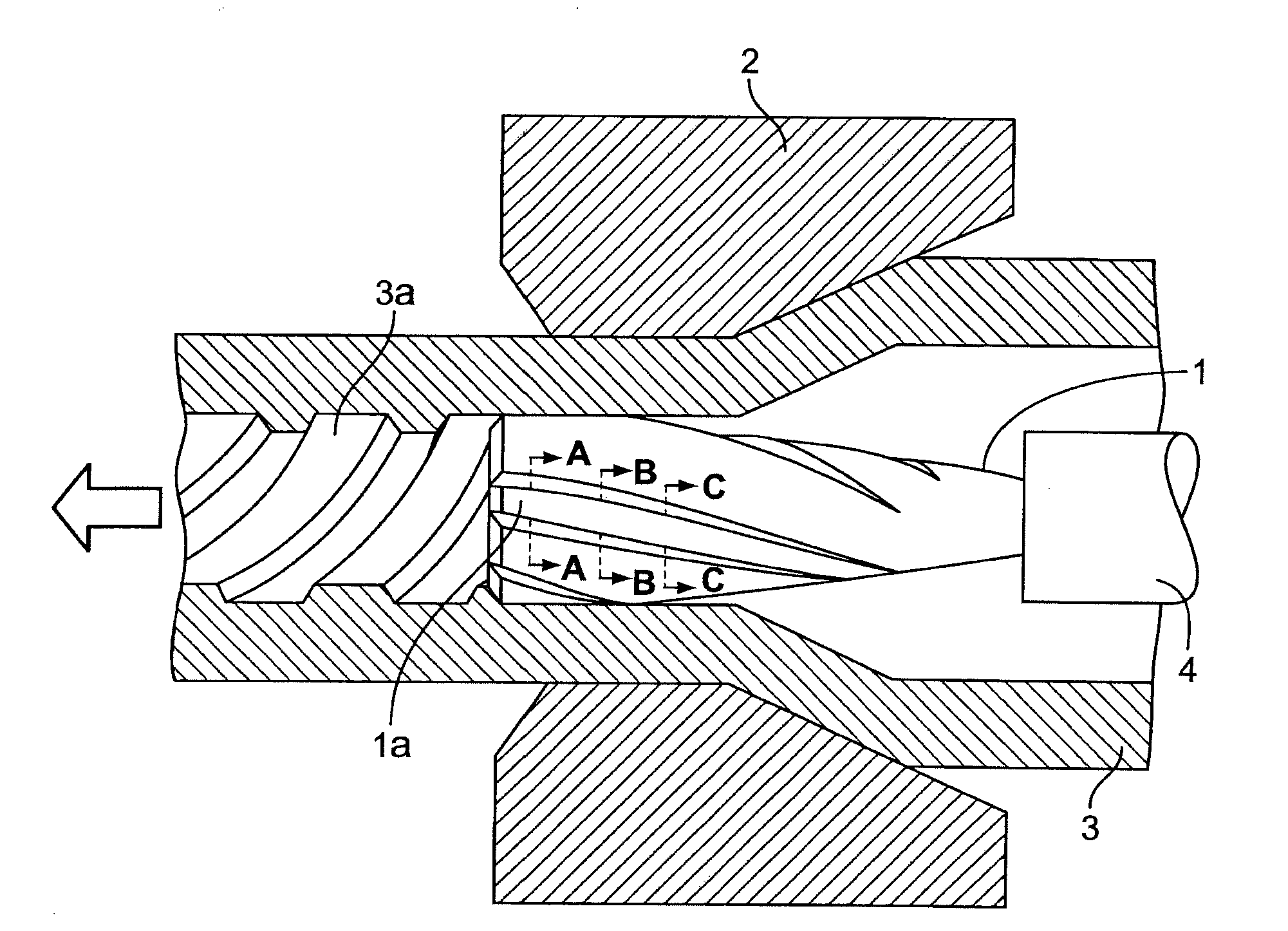
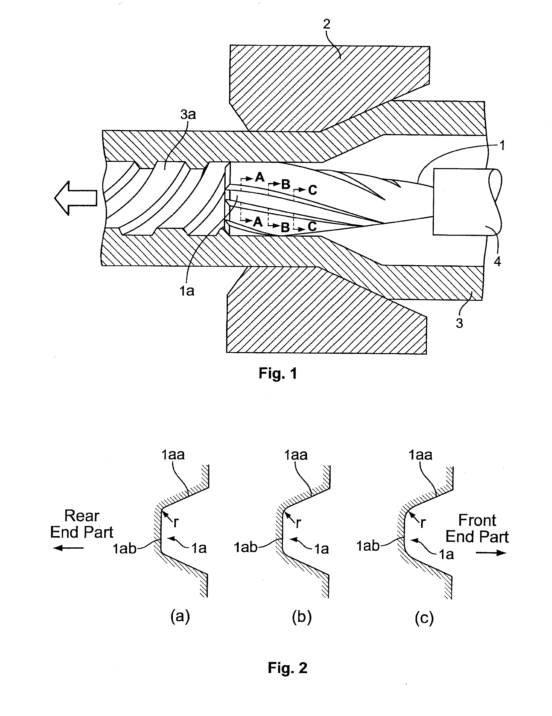
[0014]The present invention has been made to solve the above-described problems with cold drawing of internally ribbed steel tube, and accordingly an object thereof is to provide a production method of an internally ribbed steel tube, in which a drawing plug is preheated before cold drawing for forming spiral ribs, and the heating temperature therefor is controlled, whereby troubles at the time of cold drawing for forming the spiral ribs are reduced, and the spiral ribs can be formed stably.
[0019]The present inventor paid attention to the above-described technical aspects concerning the cold drawing of internally ribbed steel tube, and conducted various studies. As a result, the present inventor obtained a finding that before the cold drawing for forming the spiral ribs, the drawing plug be preheated, and the heating temperature therefor be controlled so as to be in the temperature range suitable for cold drawing locally generating an elevated-temperature zone, whereby troubles at the time of cold drawing for forming the spiral ribs can be reduced.
[0025]According to the production method of an internally ribbed steel tube in accordance with the present invention, the drawing plug is preheated before cold drawing for forming spiral ribs, and the heating temperature therefor is properly controlled, whereby troubles at the time of cold drawing for forming the spiral ribs are suppressed, and the spiral ribs can be formed stably. The internally ribbed steel tube thus obtained is excellent in formidability and quality.

Problems solved by technology

In producing the internally ribbed steel tube, however, even if optimal chemical treatment is performed on the surfaces of blank tube under proper conditions as described later, before the cold drawing for forming the spiral ribs, drawing troubles occur frequently depending on the treatment conditions of a drawing plug, and the formability and production yield of the internally ribbed steel tube may be deteriorated remarkably.

Method used


Image

  • Production method of internally ribbed steel tube and drawing plug for use therein
  • Production method of internally ribbed steel tube and drawing plug for use therein
  • Production method of internally ribbed steel tube and drawing plug for use therein

Examples


example 1

[0046]In Example 1, internally ribbed steel tubes having four stripes of spiral ribs were produced by cold drawing using a seamless steel tube blank whose steel type was JIS STBA22 (1Cr-1 / 2Mo steel) after subjecting the blank tube to a series of steps: blank tube softeningpickling / lubricating treatment—intermediate cold drawing (circle finish drawing)—softening.

[0047]The drawing schedule in this Example was such that the blank tube size was comprised by 38.0 mm in outside diameter and 8.2 mm in wall thickness, dimensions after the intermediate cold drawing were 32.0 mm in outside diameter and 7.2 mm in wall thickness, and the final product dimensions after cold drawing were 28.6 mm in outside diameter, 6.0 mm in wall thickness, and 0.8 mm in rib depth.

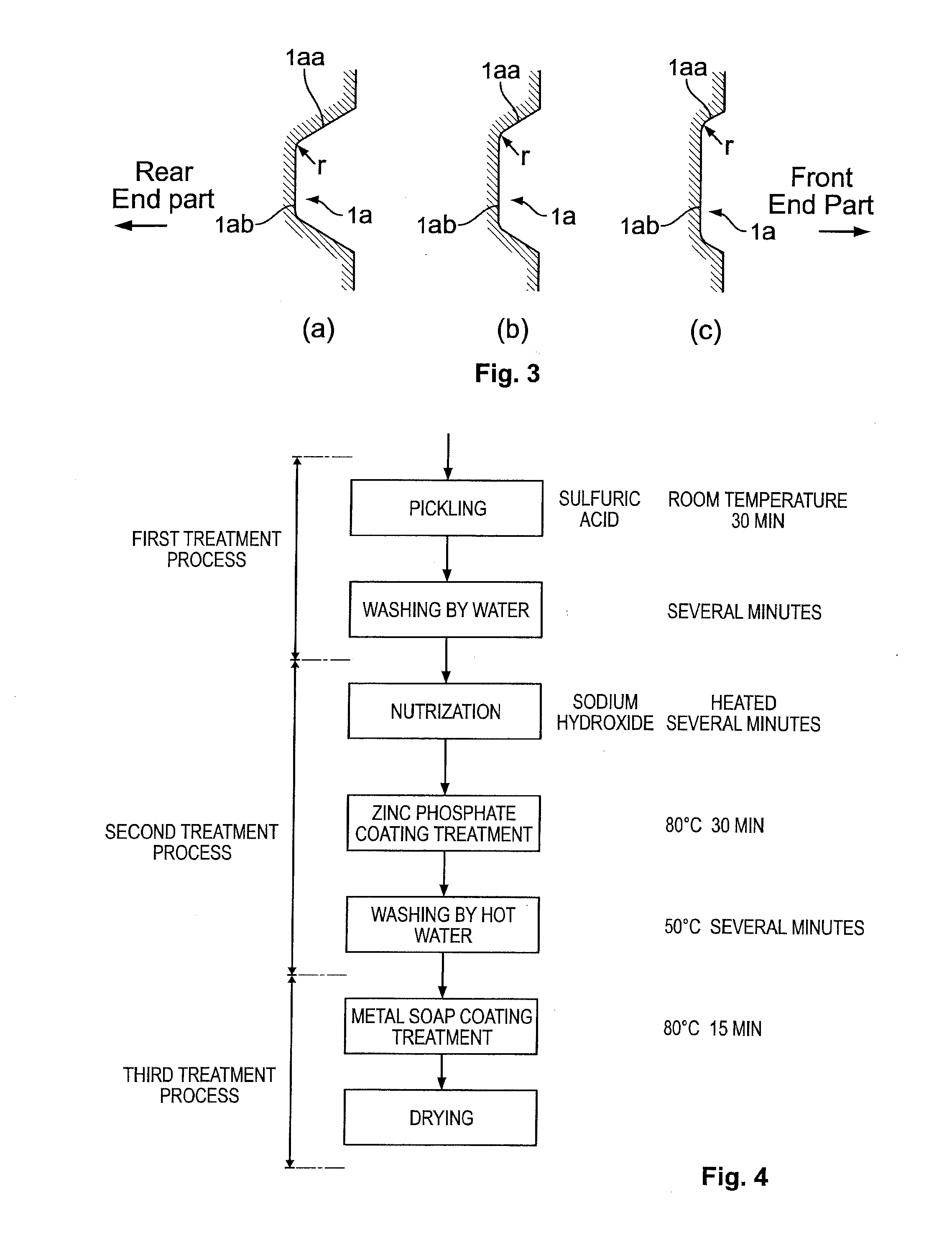
[0048]As the chemical treatment before cold drawing for finally forming the spiral ribs, pickling was performed using sulfuric acid (10 to 13%) at room temperature for 30 minutes, and after rinsing by water and neutralization, zinc ph...

example 2

[0053]In Example 2, internally ribbed steel tubes having four stripes of spiral ribs were produced by cold drawing using a seamless steel tube blank whose steel type was JIS STBA24 (2Cr-1Mo steel) after subjecting the blank tube to a series of steps: blank tube softening—pickling / lubricating treatment—intermediate cold drawing (circle finish drawing)—softening.

[0054]The drawing schedule in this Example was such that the blank tube size was comprised by 87.0 mm in outside diameter and 10.2 mm in wall thickness, dimensions after the intermediate cold drawing were 80.0 mm in outside diameter and 9.2 mm in wall thickness, and the final product dimensions after cold drawing were 70.0 mm in outside diameter, 8.0 mm in wall thickness, and 1.1 mm in rib depth.

[0055]The conditions for chemical treatment before final cold drawing for forming the spiral ribs were the same as those in Example 1. Also, the shape of the drawing plug used and the preheating of the drawing plug were the same as tho...


PUM

PropertyMeasurementUnit
Temperatureaaaaaaaaaa
Pressureaaaaaaaaaa

Abstract

There is provided a production method capable of forming spiral ribs stably by reducing troubles at the time of cold drawing for forming the spiral ribs on an internally ribbed steel tube. When the internally ribbed steel tube on which a plurality of stripes of spiral ribs are formed in the tube axis direction is manufactured by inserting a plug on which a plurality of stripes of spiral grooves are formed on the outer peripheral surface thereof into the tube to be worked subjected to chemical treatment and then performing cold drawing, drawing is performed with the plug preheated to 50 to 200° C., thus forming the spiral ribs on the internal surface of a blank tube. The chemical treatment preferably includes a pickling step of removing oxided scale and rust on the tube surface, a step of forming a zinc phosphate coat on the neutralized tube surface, and a step of forming a lubricating layer on the zinc phosphate coat. The internally ribbed steel tube thus obtained is well applicable to increased capacity and higher temperature / higher pressure of a boiler because the steel tube is provided with formability and quality excellent as a boiler steel tube.

Description

TECHNICAL FIELD[0001]The present invention relates to a production method of an internally ribbed steel tube, forming spiral ribs (protrusions) on the internal surface of a steel tube by cold drawing, and a drawing plug therefor. More particularly, the invention relates to a production method of an internally ribbed steel tube, capable of forming spiral ribs stably, and a drawing plug for use in the production method.BACKGROUND ART[0002]Usually, for a high temperature heat resistant part of a boiler, a heat exchanger, or the like, an internally ribbed steel tube (rifled tube) with spiral ribs (protrusions) formed on the internal surface of the steel tube is used to improve a power generation efficiency. Since the internal surface of the internally ribbed steel tube has a larger surface area by the ribs formed on the internal surface, a contact area between water vapor passing through the inside of heated tube and the internal surface of the tube increases, while allowing turbulence ...

Claims


Application Information

Patent Timeline
IPC IPC(8): B21C3/16B21C37/20B21B45/04
CPCB21C1/24F28F2245/00B21C37/207C10M129/40C10M2201/085C10M2207/125C10M2207/1253C10N2230/06C10N2240/403C10N2250/14C21D8/10C21D9/08F28F1/40F28F19/06B21C3/16C10N2030/06C10N2040/241C10N2050/023
Inventor BEPPU, KENICHI
Owner NIPPON STEEL CORP
Learn More