Prism unit and laser device

a laser device and prism technology, applied in the field of laser devices, can solve the problems of reducing the diffraction loss, and reducing the output power of the laser light b>21/b>, so as to reduce the diffraction loss, reduce the resonator length of the laser device, and increase the output power of the laser light

Inactive Publication Date: 2006-02-28
GIGAPHOTON
View PDF15 Cites 1 Cited by
  • Summary
  • Abstract
  • Description
  • Claims
  • Application Information

AI Technical Summary

Benefits of technology

[0019]The laser device according to the present invention includes the above-described prism unit, and only a wavelength in a desired range out of a plurality of oscillation wavelengths is selectively oscillated by the prism unit. According to the constitution, the prism unit is reduced in size, and therefore the resonator length of the laser device becomes small. Accordingly, the diffraction loss is reduced, and the output power of the laser light is increased.

Problems solved by technology

However, the above-described prior art has the problems as described as follows.
In addition, resonator length that is the distance between the front mirror 16 and the rear mirror 18 becomes longer, and therefore there arises the problem that output power of the laser light 21 is reduced by the diffraction loss.
As a result, a wavefront is disturbed to cause wave aberration, and line select is not favorably performed, or reduction in output power of the laser light 21 is sometimes caused.

Method used


Image

  • Prism unit and laser device
  • Prism unit and laser device
  • Prism unit and laser device

Examples


first embodiment

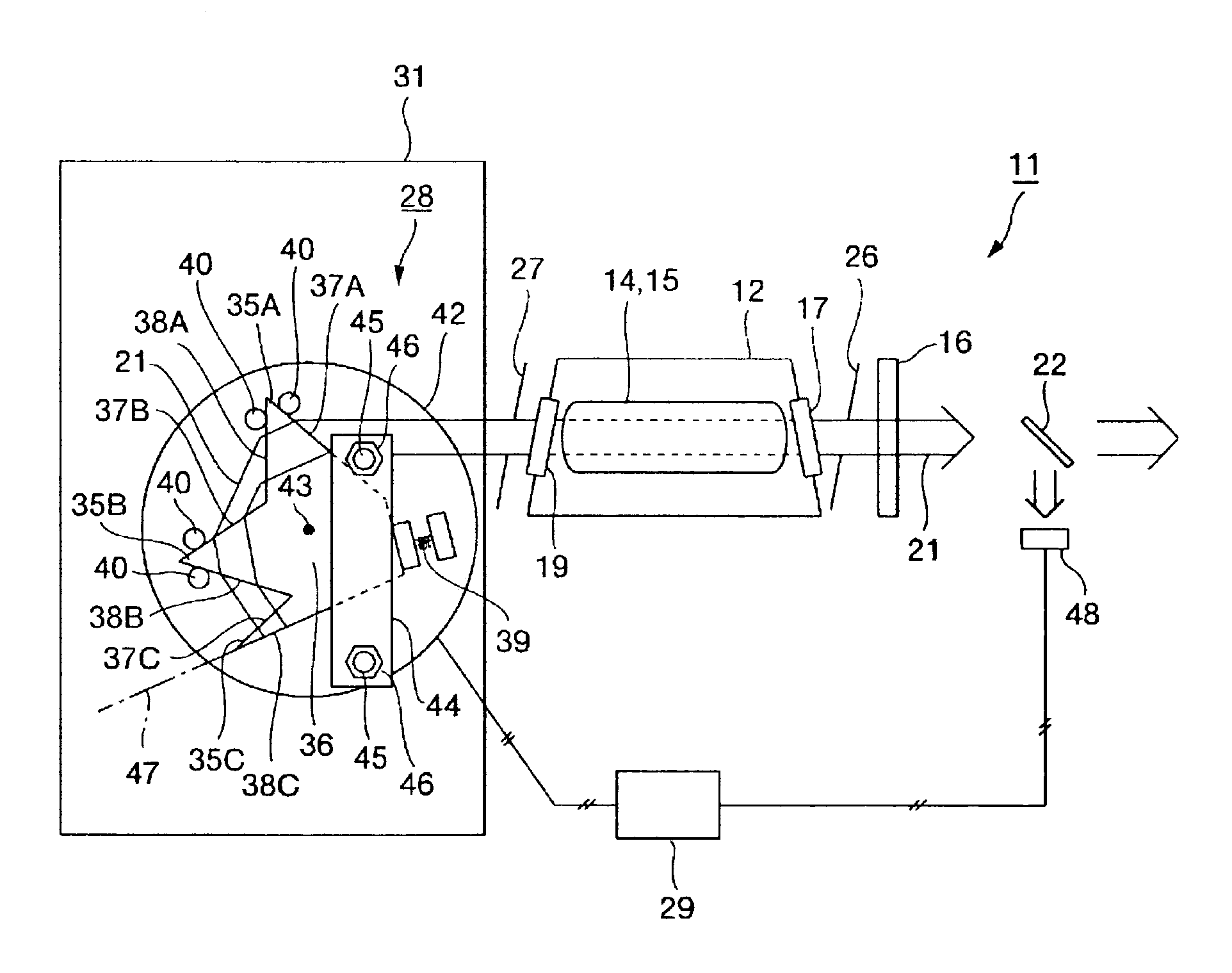
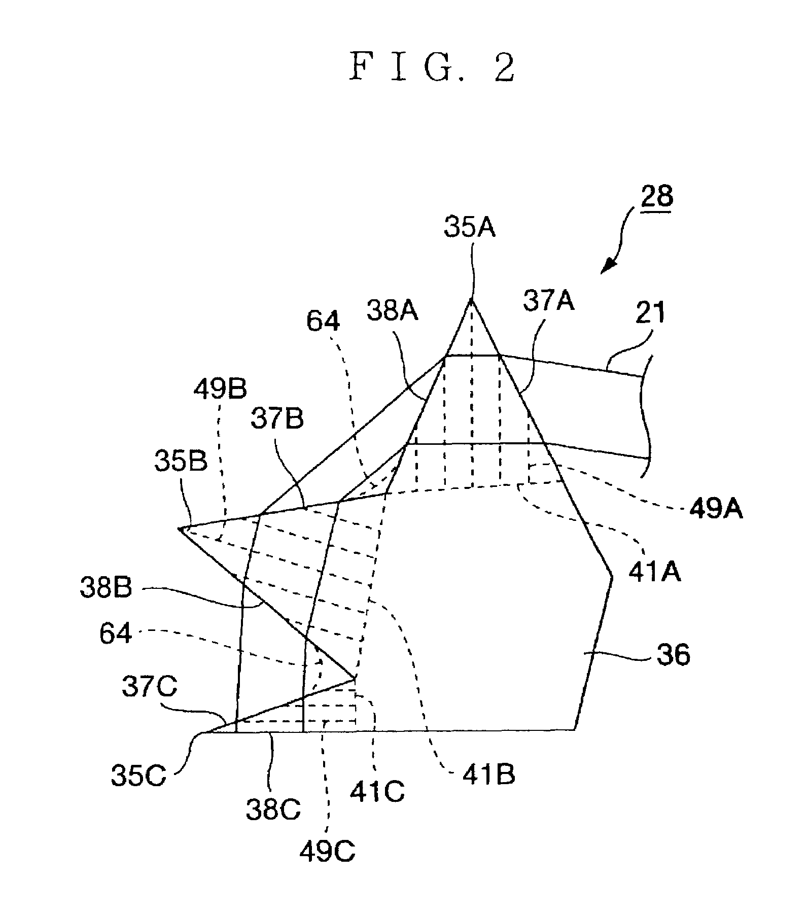
[0031]First, a first embodiment will be explained. FIG. 1 shows a block diagram of the molecular fluorine laser device with use of a dispersing prism unit according to the embodiment. In FIG. 1, a molecular fluorine laser device 11 includes a laser chamber 12 in which a laser gas containing fluorine (F2) is sealed. Windows 17 and 19 through which laser light (molecular fluorine laser light) 21 is transmitted are provided at a front and a rear parts of the laser chamber 12.

[0032]Slits 26 and 27 are placed in front of and behind the laser chamber 12. A front mirror 16 which partially transmits the laser light 21 is placed in front of the laser chamber 12. Each of the slits 26 and 27 is formed of metal such as aluminum for the purpose of shielding light. It is desirable that the slits 26 and 27 are each placed by being inclined at an angle of a fixed value or more from the perpendicular (for example, three degrees or more) with respect to an optical axis of the laser light 21 to preven...

third embodiment

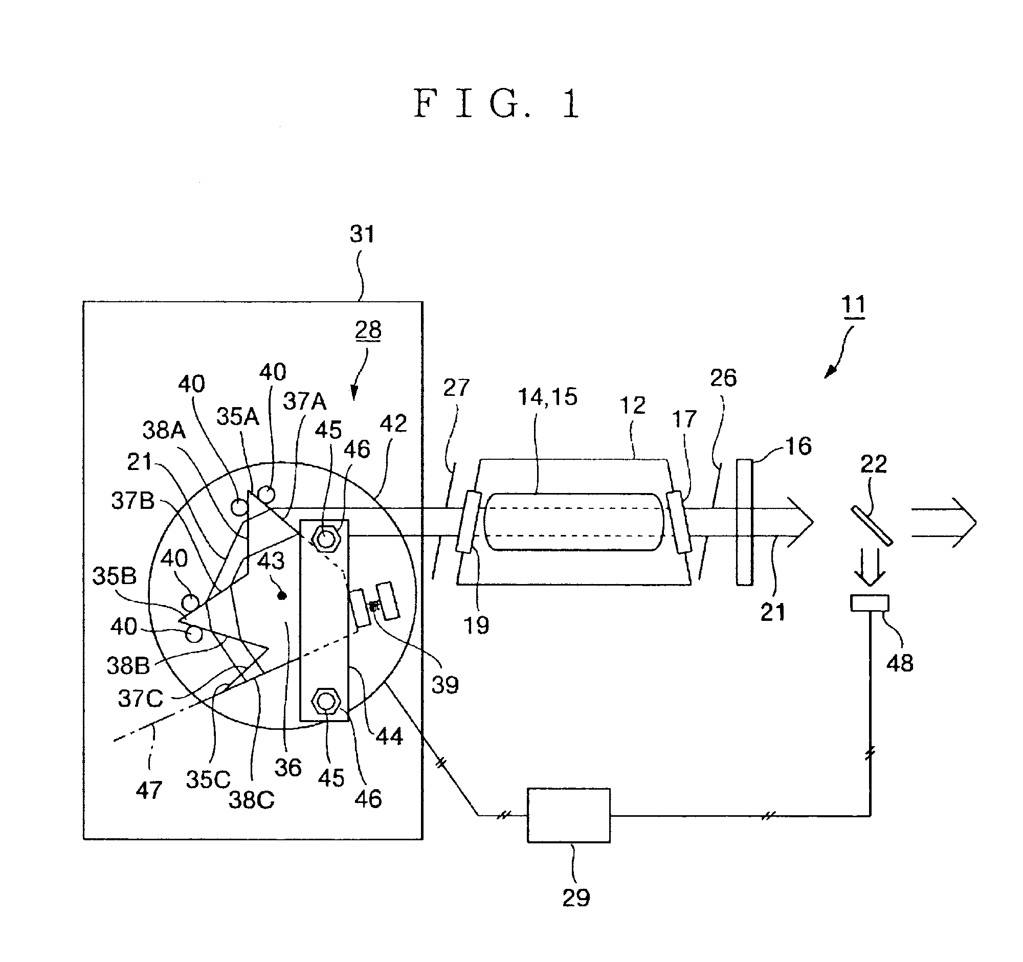
[0066]As explained above, coating is not applied to the dispersing prism unit 28, and thereby the third incidence plane 37C forms a front mirror, which partially transmits the laser light 21. As a result, all the components of the laser light 21 generated inside the laser chamber 12 passes through the dispersing prism parts 35A to 35C of the dispersing prism unit 28 before they are emitted.

[0067]Namely, in the first and the second embodiments, only a part of the laser light 21 is transmitted through the front mirror 16 directly from the laser chamber 12 and emitted, and therefore the components which are not band-narrowed sometimes mix into the emitted laser light 21. On the other hand, in the third embodiment, all the laser light 21 passes through the dispersing prism unit 28, where it is band-narrowed, and therefore impure components do not mix into the emission light, and the spectrum purity becomes high. In this situation, coating which partially reflects the laser light 21 may...


PUM


Abstract

A prism unit, which is capable of firmly fixing a plurality of prism parts in a small space, and a laser device, which is capable of enhancing output power of laser light with use of the prism unit, are provided. For this purpose, a prism unit (28) includes a plurality of prism parts (35), which refract incident light (21), and a fixed part (36) which is fixed to or formed integrally with at least two of the plurality of prism parts. Further, a laser device includes the prism unit (28), and only a wavelength in a desired range out of a plurality of oscillation wavelengths is selectively oscillated by the prism unit.

Description

TECHNICAL FIELD[0001]The present invention relates to a laser device in which a wavelength is band-narrowed or line-selected, and a prism used therefor.BACKGROUND ART[0002]Conventionally, means for performing wavelength selection (line selection) for laser light with use of a dispersing prism, and narrowing spectral line width thereof is known, and, for example, document, Canadian Journal of Physics Vol.63.1985 (pp.214–219) shows the one. FIG. 10 shows a plan view of a molecular fluorine laser device in which spectral line width is narrowed with use of line select means disclosed in the aforementioned document, and the prior art will be explained hereinafter based on FIG. 10.[0003]In FIG. 10, a molecular fluorine laser device 11 includes a laser chamber 12 in which a laser gas that is a laser medium is sealed. The laser gas contains fluorine (F2) and a buffer gas with predetermined composition. As the buffer gas, helium (He), neon (Ne), or a mixture gas of both of them is generally ...

Claims


Application Information

Patent Timeline
Patent Type & Authority Patents(United States)
IPC IPC(8): G02B5/04H01S3/08H01S3/223
CPCG02B5/04H01S3/105H01S3/08004
Inventor WAKABAYASHI, OSAMUSOUMAGNE, GEORGKUMAZAKI, TAKAHITO
Owner GIGAPHOTON
Why Eureka
Try Eureka