Changing and shaping method for plate strip wave guide laser output laser beam

A technology of waveguide lasers and laser beams, which is applied in the field of lasers and can solve problems such as complex production, poor beam roundness, and large diffraction loss

Active Publication Date: 2007-12-19
BEIJING BDHLASER SCI & TECH
View PDF3 Cites 0 Cited by
  • Summary
  • Abstract
  • Description
  • Claims
  • Application Information

AI Technical Summary

Problems solved by technology

This method is to combine two pairs of four cylindrical mirrors to form two sets of telescope systems. Each set of telescope systems performs shaping transformation on the direction of the laser beam parallel to the slab waveguide and perpendicular to the direction of the slab waveguide. This method is also It is more complex, and the roundness of the transformed beam is poor
The third method is to use the method of binary optics to make the beam conversion element, but at the current production level, the diffraction loss is relatively large

Method used


Image

  • Changing and shaping method for plate strip wave guide laser output laser beam
  • Changing and shaping method for plate strip wave guide laser output laser beam
  • Changing and shaping method for plate strip wave guide laser output laser beam

Examples


Embodiment 1

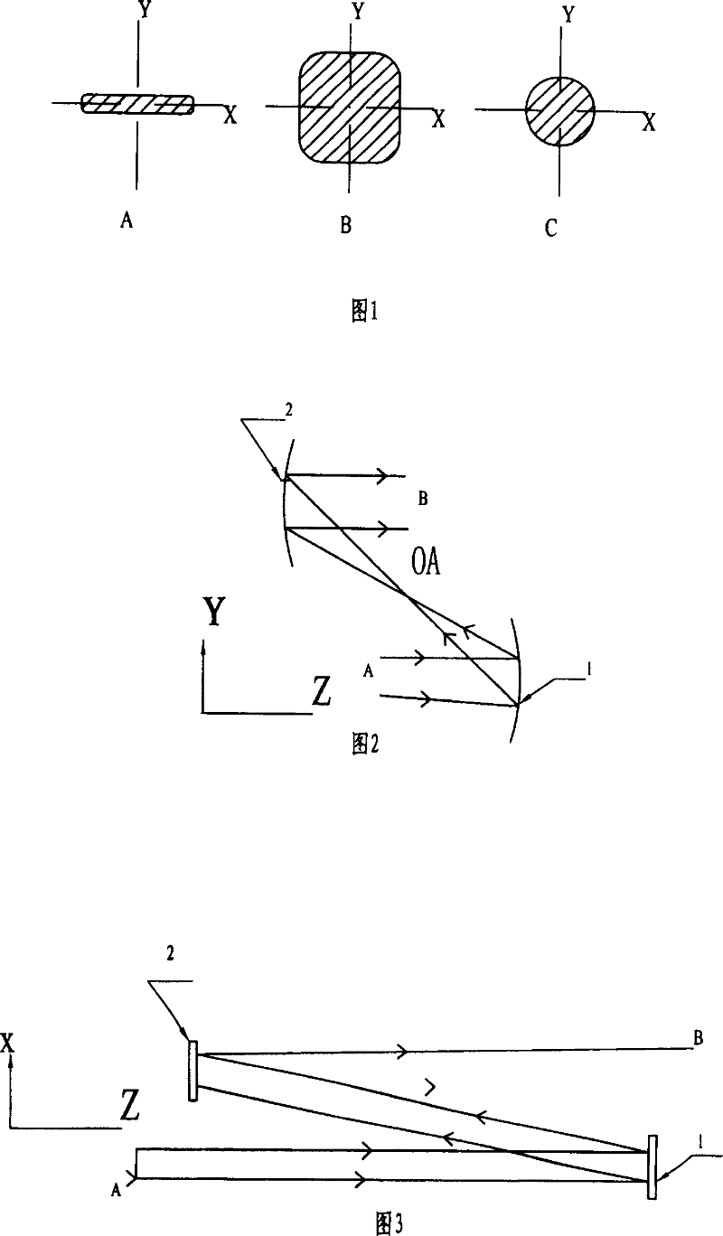
[0070] Diffusion-cooled slab waveguide CO in kilowatt-level RF excitation 2 In the laser, due to the use of an off-axis unstable cavity, it is a quasi-parallel beam output by the unstable cavity in the direction parallel to the slab waveguide (X direction), and a quasi-parallel beam in the direction perpendicular to the slab waveguide (Y direction). Gaussian distributed laser beam, the output laser beam cross section is rectangular at the waveguide port. Quasi-parallel beam radius ω in the direction parallel to the slab waveguide (Y direction) X01 is 12mm, the Gaussian-like laser beam radius ω perpendicular to the slab waveguide direction (Y direction) Y01 is 0.65mm. The output wavelength is 10.6um. The transform shaping process is as follows:

[0071] the focal length f Yc1 The first cylindrical reflector is placed at the waveguide port A at a distance L of 300mm 0 place, L 0 It is 1400mm.

[0072] Calculated according to formulas (2) and (3):

[0073] Y-direction sp...

Embodiment 2

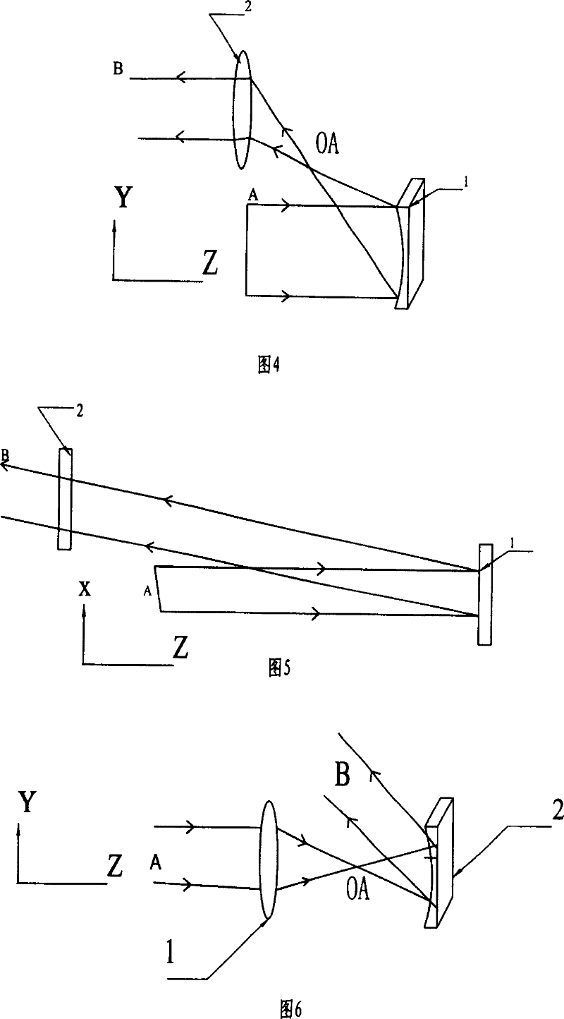
[0077] Slab waveguide CO 2 The output laser beam cross section and transformation shaping method in the laser are the same as in embodiment 1, the difference is that the beam wavelength is 9.6um, and the focal length f Yc1 50mm, L 0 55mm, K 1 =0.5, the focal length of the second cylindrical mirror is f Yc2 lens. The calculation method of the parameters is the same as in Example 1 (see Fig. 4, Fig. 5).

Embodiment 3

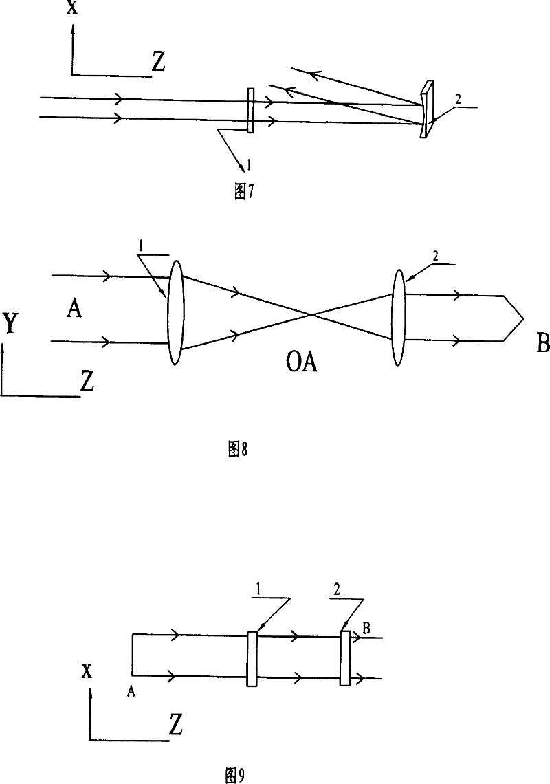
[0079] The slab waveguide solid-state laser, the output laser beam and the transformation and shaping method are the same as the embodiment 1, the difference is that the beam wavelength is 1.064um, and the first cylindrical mirror is a lens with a focal length f Yc1 80mm, L 0 500mm, K 1 =2. The calculation method of the parameters is the same as in Example 1. (See Figure 6, Figure 7)


PUM


Abstract

Present invention relates to a strip waveguide laser outgoing laser conversion reshape method. Present invention uses two cylindrical mirror or cylindrical lens constituting one dimension directional extend beam system, making extend beam to short arm direction of rectangular cross section light beam, to form foursquare cross section light beam then utilizing two spherical reflector or spherical lens to form two-dimensional directional extend beam system, to convert foursquare cross section light beam into required size, at the same time setting one round or variety shape spatial filter on intermediate focus accessory of two spherical reflector or spherical lens, to make output beam cross section becoming circular symmetry or variety shape. Reshaped light beam can be widely used to laser technology field.

Description

technical field [0001] The invention relates to a method for transforming and shaping the output laser beam of a laser, in particular to a method for transforming and shaping the output laser beam of a slab waveguide laser. It belongs to the field of lasers. Background technique [0002] In the slab waveguide laser, due to the use of an unstable cavity structure, in the direction parallel to the slab waveguide, it is a wide-width quasi-parallel beam output by the unsteady cavity, and in the direction perpendicular to the slab waveguide, it is a waveguide mode with Gaussian distribution. Laser beam, the cross-section of the output laser beam is a rectangular distribution. The rectangular beam distribution limits the application of slab waveguide lasers. In many laser technology applications, the circularly symmetrical distribution of the cross-section is a very important indicator of the laser. Transforming the rectangular beam shaping into a circular symmetrical beam expan...

Claims


Application Information

Patent Timeline
Patent Type & Authority Patents(China)
IPC IPC(8): H01S3/00H01S3/10H01S5/00G02F1/35G02F1/29
Inventor 辛建国邬江兴张志远王伟平
Owner BEIJING BDHLASER SCI & TECH
Why Eureka
Try Eureka