
Side grating based light coupling system

a technology of light coupling and side grating, which is applied in the direction of instruments, cladded optical fibres, optical elements, etc., can solve the problems of difficult improvement of coupling light efficiency and final energy conversion efficiency, and the relevant industry would have additional manufacturing costs, so as to reduce secondary diffraction loss and scattering loss, improve energy conversion efficiency, and reduce cost

Inactive Publication Date: 2017-05-25
NAT TAIPEI UNIV OF TECH
View PDF0 Cites 0 Cited by
  • Summary
  • Abstract
  • Description
  • Claims
  • Application Information

AI Technical Summary

Benefits of technology

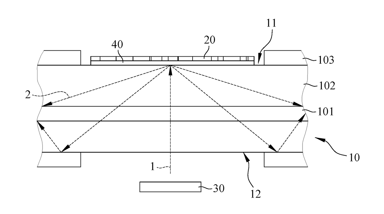
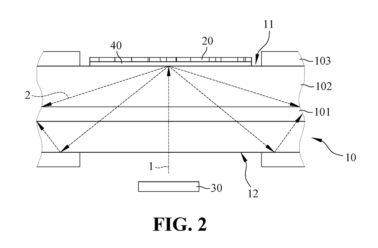
The present invention provides a side grating based light coupling system that reduces secondary diffraction loss and scattering loss due to edge without using an optical collimating lens. This system reduces production costs, wear and tear, and improves energy conversion efficiency. By arranging grating elements in non-uniform arrangement, the system reduces the secondary diffraction loss and scattering loss due to edge, thereby achieving the purpose of reducing cost to improve energy conversion efficiency.

Problems solved by technology

Therefore, relevant industry would have additional manufacturing costs, rather than in line with the production of cost-effectiveness.
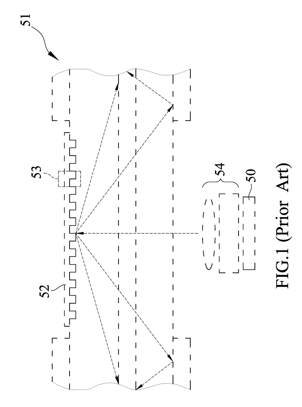
On the other hand, since the technology of the prior art is limited to the specific periodic structure parameters of the grating elements, the secondary diffraction loss and scattering loss due to edge are inevitable, so that the efficiency of coupling light and final energy conversion efficiency are difficult to improve.

Method used


Image

  • Side grating based light coupling system
  • Side grating based light coupling system
  • Side grating based light coupling system

Examples


Embodiment Construction

[0020]Hereinafter, described embodiments of the present invention by certain specific embodiments, the person skilled in the art can easily understand other advantages and efficacy of the present invention disclosed by this specification of the content. The present invention can also be implemented or applied by other different specific examples. The details of the invention may also be a variety of modifications and changes, based on different perspectives and application, and without departing from the spirit of the present invention.

[0021]Notice, the structure, proportion, size, etc. in drawings of the present invention are only to fit the disclosed contents of the present invention, for persons familiar with this art to understanding and reading, not intended to limit the qualification of the present invention may be implemented. Therefore, no real meaning of the technology with any modification of the structure, proportion, size, etc. In the case of it does not affect the effic...


PUM


Abstract

A side grating based light coupling system comprises an optical fiber, a side grating disposed on one side of the lateral wall of the optical fiber, and a laser array disposed adjacent to the other side of the lateral wall of the optical fiber. The side grating comprises a plurality of grating elements arranged in a non-uniform arrangement. The laser array for generating a laser beam towards and passes through the optical fiber, and the laser beam is converted into at least one laser beam through the plurality grating elements. The diffraction efficiencies of the converted laser beams are different. The converted laser beams propagate inside the optical fiber based on total internal reflection. The plurality of grating elements of the side grating are heterogeneous arrangement without loading the optical collimating lens, and can reduce scattering loss by controlling the asymmetric diffraction efficiency, to improve optical coupling efficiency.

Description

CROSS-REFERENCE TO RELATED APPLICATION[0001]This application claims the priority of Taiwanese patent application No. 104139127, filed on Nov. 25, 2015, which is incorporated herewith by reference.BACKGROUND OF THE INVENTION[0002]1. Field of the Invention[0003]The present invention relates to a side grating based light coupling system, especially a side grating based light coupling system with the asymmetric diffraction efficiencies.[0004]2. The Prior Arts[0005]In Taiwan Patent No. 200947002 “Gratings At Optical Fiber Side And Coupling Apparatus Using The Same”, the invention describes the conventional technology which is to provide a grating at optical fiber side and coupling apparatus. As shown in FIG. 1, a fiber side-coupling apparatus comprises: a semiconductor laser diode bar array 50, disposed at one side of an optical fiber 51, producing pump beams and through optical collimation system 54; and a cladding grating 52. The cladding grating 52 comprises: a plurality of grating me...

Claims


Application Information

Patent Timeline
IPC IPC(8): G02B6/02G02B6/34
CPCG02B6/34G02B6/02061G02B6/4214H01S3/094019H01S3/0941
Inventor LEE, YIN-WENHUANG, SHENG-LUNGLI, YEN-YIN
Owner NAT TAIPEI UNIV OF TECH
Learn More