An optical resonant cavity composed of non-parallel mirrors and a method for generating optical resonance

An optical resonant cavity and flat mirror technology, applied in the field of optoelectronics, can solve the problems of large diffraction loss and geometric loss, uneven beam intensity distribution, complex manufacturing process, etc., achieve small line width, reduce diffraction loss, large Q effect of value

Active Publication Date: 2019-05-17
BEIJING UNIV OF POSTS & TELECOMM
View PDF6 Cites 0 Cited by
  • Summary
  • Abstract
  • Description
  • Claims
  • Application Information

AI Technical Summary

Problems solved by technology

[0003] In the prior art, common resonators include parallel plane optical resonators and spherical optical resonators. Parallel plane optical resonators are simple to manufacture, have good beam directionality, and relatively uniform light field distribution in the cavity. The loss and geometric loss are relatively large; the spherical optical resonator has a small diffraction loss compared to the parallel plane resonator, and it is easy to obtain a single-ended output and collimated parallel beam, but the beam intensity distribution is not uniform, and the manufacturing process is more complicated

Method used


Image

  • An optical resonant cavity composed of non-parallel mirrors and a method for generating optical resonance
  • An optical resonant cavity composed of non-parallel mirrors and a method for generating optical resonance
  • An optical resonant cavity composed of non-parallel mirrors and a method for generating optical resonance

Examples


Embodiment Construction

[0022] In order to make the purpose, technical solutions and advantages of the embodiments of the present invention clearer, the technical solutions in the embodiments of the present invention will be clearly described below in conjunction with the accompanying drawings in the embodiments of the present invention. Obviously, the described embodiments are the Some, but not all, embodiments are invented. Based on the embodiments of the present invention, all other embodiments obtained by persons of ordinary skill in the art without making creative efforts belong to the protection scope of the present invention.

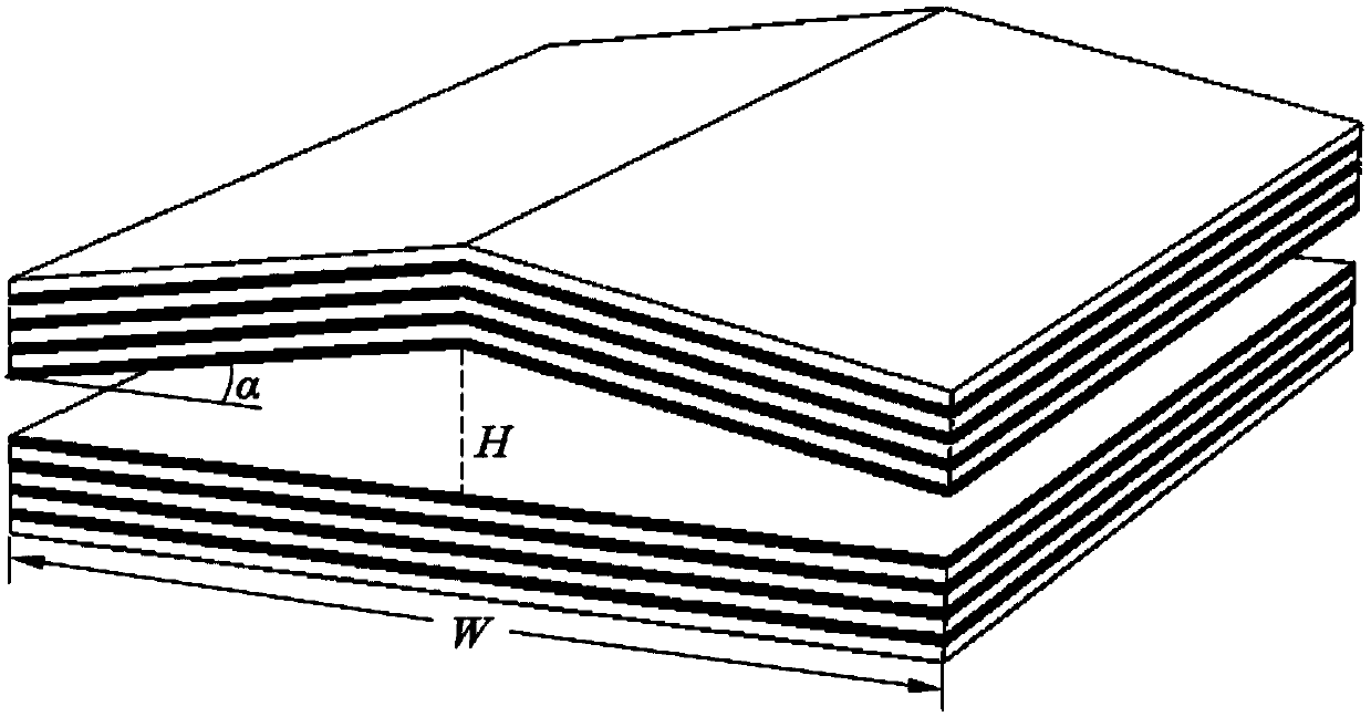
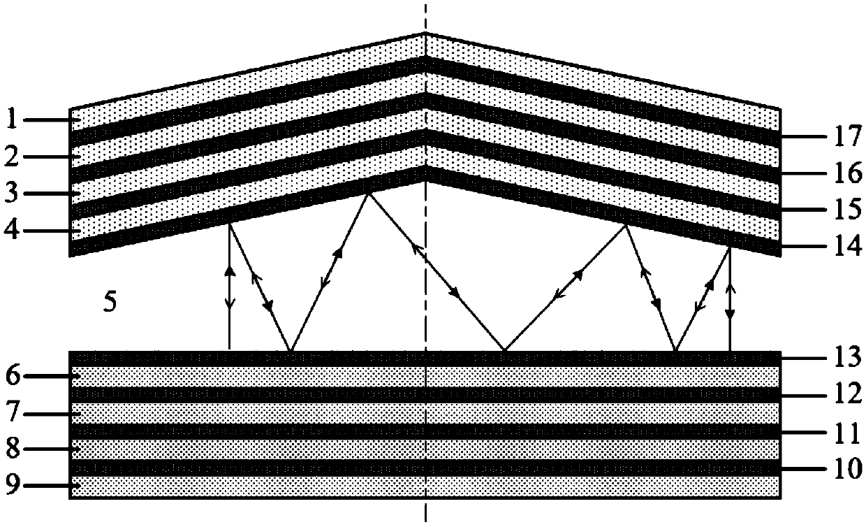
[0023] An embodiment of the present invention provides an optical resonant cavity, including: a top reflector and a bottom reflector, a cavity is formed between the top reflector and the bottom reflector, and a medium is filled in the cavity; the top reflector It includes two plane reflectors arranged oppositely, and the two plane reflectors have the same inclination an...


PUM


Abstract

The invention provides an optical resonant cavity formed by non-parallel reflecting mirrors and a method for generating optical resonance. The optical resonant cavity comprises a top reflecting mirror and a bottom reflecting mirror, and is characterized in that a cavity is formed between the top reflecting mirror and the bottom reflecting mirror, and the cavity is filled with a medium; the top reflecting mirror comprises two oppositely arranged plane reflecting mirrors, and the two plane reflecting mirrors have the same inclination angle relative to the bottom reflecting mirror; and the bottom reflecting mirror is a plane reflecting mirror. According to the invention, the resonant cavity is provided with the inclined top reflecting mirror, so that an incident beam perpendicular to the bottom reflecting mirror is enabled to be increased in optical path during reproduction in the process of advancing in the resonant cavity. The optical resonant cavity provided by the invention has different resonance conditions from a parallel plane resonant cavity, and can acquire small linewidth and a greater Q-value. In addition, the optical field energy can be effectively controlled within a certain area, and the diffraction loss is reduced.

Description

technical field [0001] The invention relates to the field of optoelectronic technology, in particular to an optical resonant cavity composed of non-parallel mirrors that can be used in optoelectronic devices such as lasers or filters, and a method for generating optical resonance. Background technique [0002] Since the advent of laser technology, the research on optical resonators has attracted much attention, and its theory and application have greatly promoted the development of modern optical technology. The optical resonator is an important part of the laser, and its main function is to provide optical positive feedback and control the oscillating beam. In addition, optical resonators are also widely used, designed and improved in photodetectors, filters, and photosensors. Resonators that meet various needs and have excellent performance have always been a research hotspot. [0003] In the prior art, common resonators include parallel plane optical resonators and spher...

Claims


Application Information

Patent Timeline
Patent Type & Authority Patents(China)
IPC IPC(8): H01S5/125
CPCH01S5/125
Inventor 黄永清段晓峰武刚李宫清张帅任晓敏刘凯毛少娟蔡世伟王欢欢
Owner BEIJING UNIV OF POSTS & TELECOMM
Why Eureka
Try Eureka