Movable floor apparatus for vehicle

a technology for moving floor and vehicle, which is applied in the direction of roofs, mechanical control devices, instruments, etc., can solve the problems of occupants with particularly large bodies and likely to have difficulty in ensuring a correct seating posture, and achieve the effect of enhancing flexibility

Inactive Publication Date: 2010-05-11
MAZDA MOTOR CORP +2
View PDF33 Cites 10 Cited by
  • Summary
  • Abstract
  • Description
  • Claims
  • Application Information

AI Technical Summary

Benefits of technology

[0007]In view of the above circumstances, it is an object of the present invention to provide a movable floor apparatus for a vehicle, capable of allowing a lowermost height position of a movable board which is disposed beneath feet of an occupant seated in an occupant seat, in a liftable and lowerable manner, to be set at a lower level so as to cope with various seating postures with enhanced flexibility.

Problems solved by technology

Thus, an occupant with particularly large body size (e.g., a tall occupant) is likely to have difficulty in ensuring a correct seating posture.

Method used


Image

  • Movable floor apparatus for vehicle
  • Movable floor apparatus for vehicle
  • Movable floor apparatus for vehicle

Examples


first embodiment

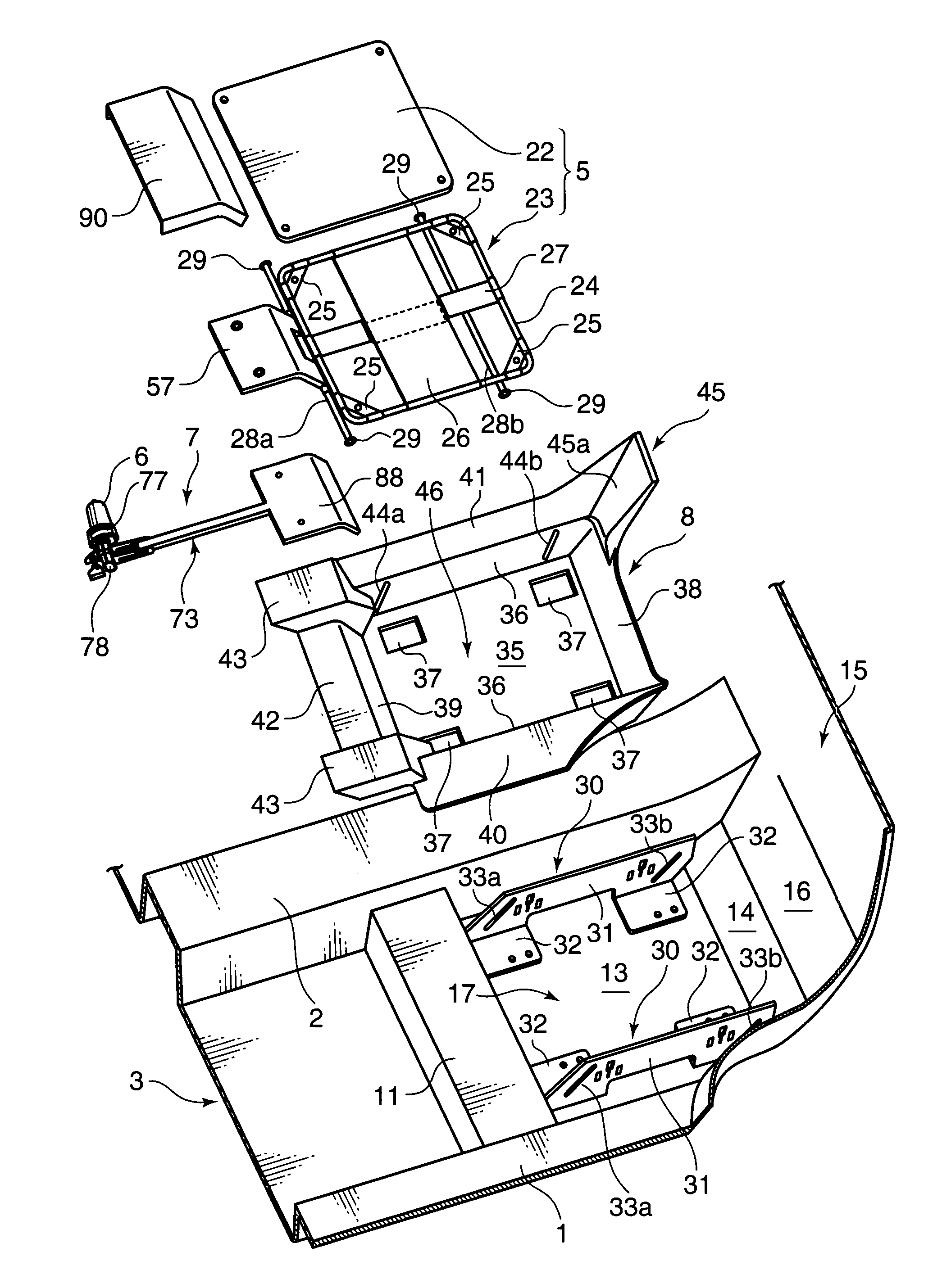
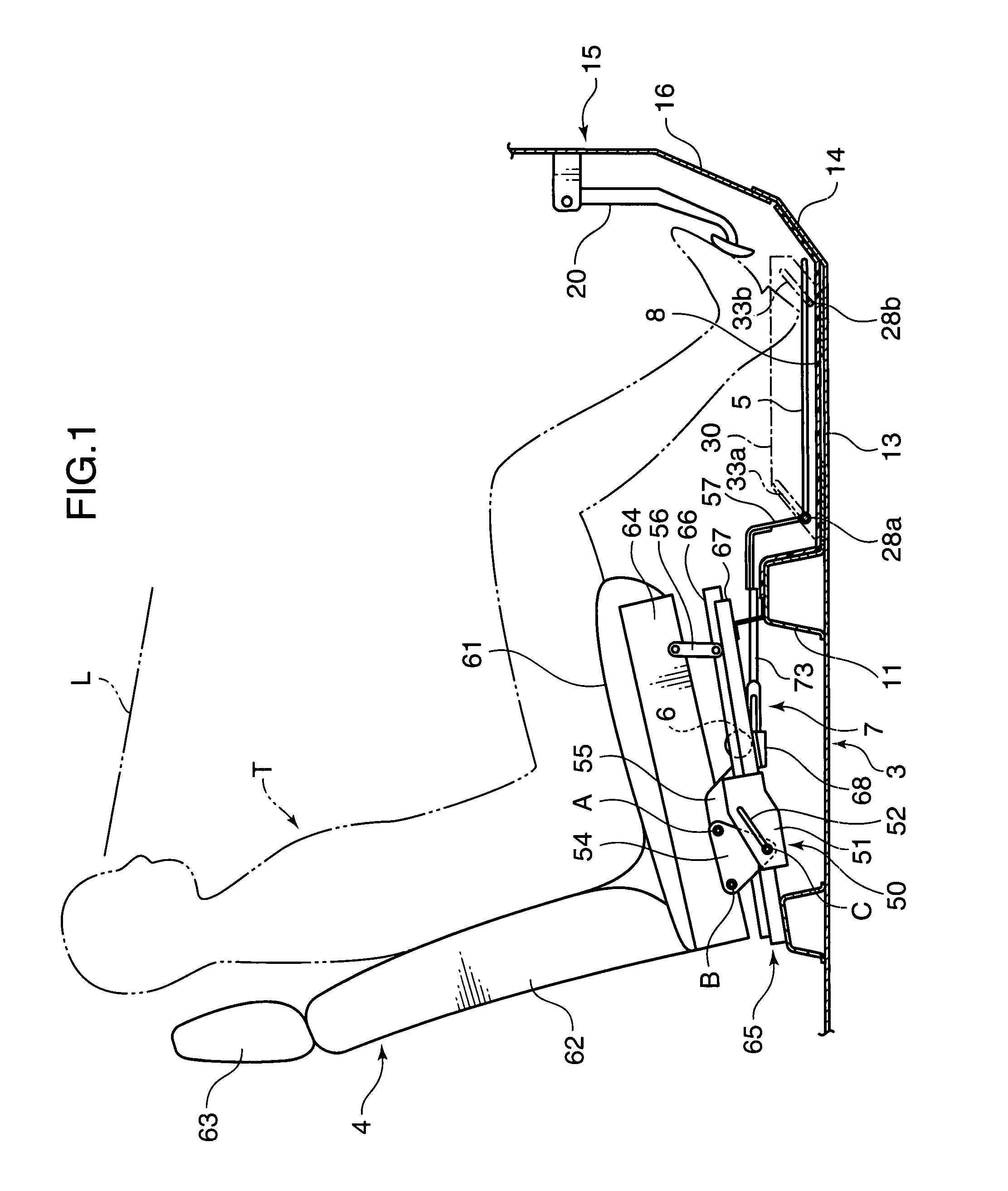
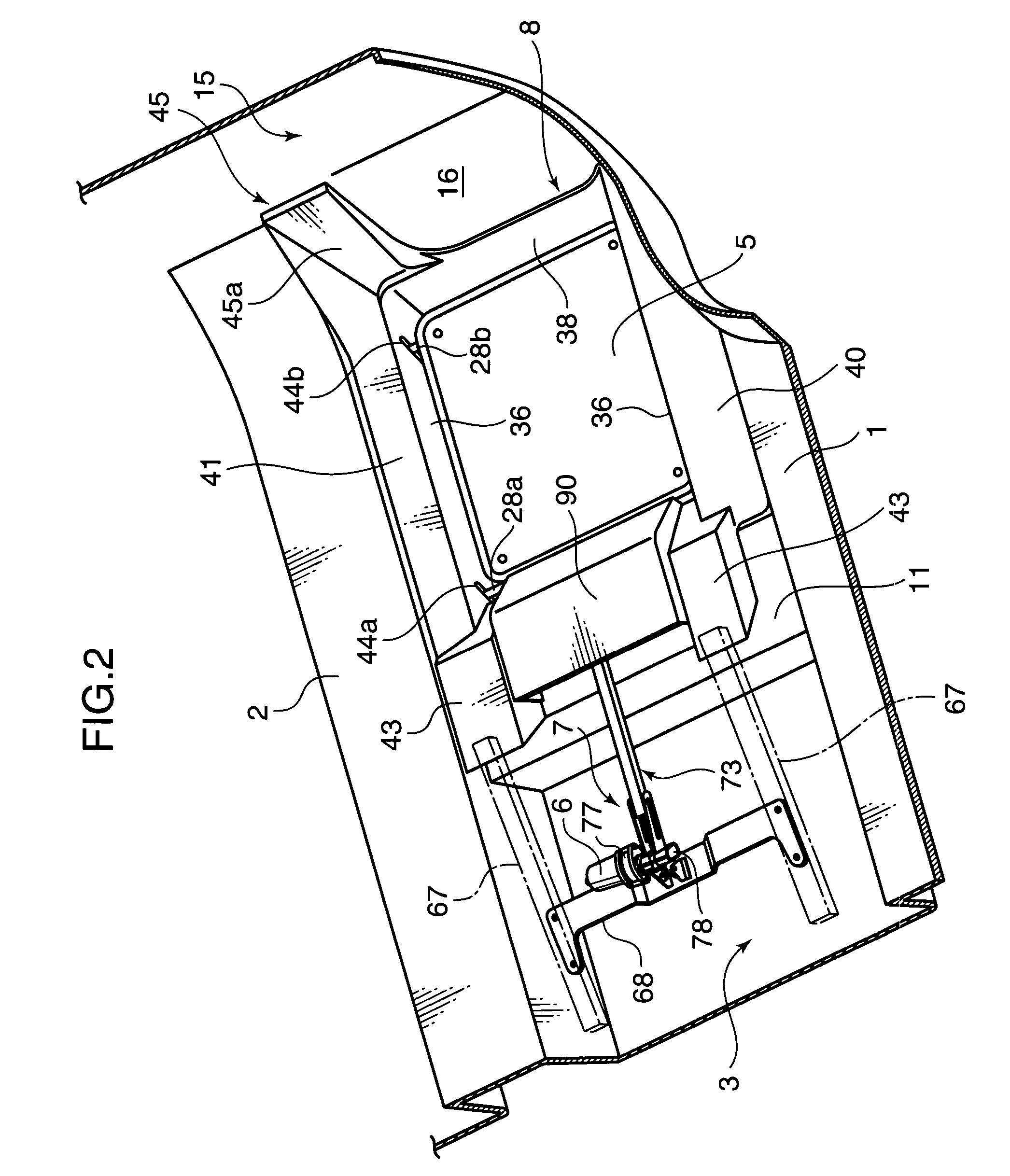
[0027]FIGS. 1 and 2 show a movable floor apparatus according to a first embodiment of the present invention. This movable floor apparatus comprises a movable board 5 which is disposed beneath feet of an occupant seated in an occupant seat 4 (hereinafter referred to occasionally as “seat occupant”), such as a driver seat, to cover an upper surface of a vehicle body floor 3 in a liftable and lowerable manner, an electric motor 6 disposed below the occupant seat 4 to serve as a drive source 6 for selectively lifting and lowering the movable board 5, and a driving-force transmission mechanism 7 adapted to transmit a driving force of the electric motor 6 to the movable board 5.

[0028]As shown in FIGS. 1 to 3, the vehicle body floor 3 comprises an approximately flat panel formed between a side sill 1 extending in a frontward / rearward (i.e., longitudinal) direction of a vehicle body along each of right and left lateral edges of the vehicle body, and a floor tunnel 2 extending in the frontwa...

second embodiment

[0088]In the first embodiment, as guide means to guide the upward / downward movement of the movable board 5, the guide grooves 33a, 33b to be penetrated by respective ones of the support shafts 28a, 28b of the movable board 5 are formed in the standing wall 31 of each of the support members 30, 30, and the lateral movement of each of the support shafts 28a, 28bis restricted by the speed nut 29 attached to each of the right and left ends of the support shafts 28a, 28b. In this structure, if one or both of the support members 30, 30 are mounted on the vehicle body floor 3 in incorrect positions to cause an misalignment in relative position between the rear guide grooves 33a, 33a and between the front guide grooves 33b, 33b in the standing wall 31, each of the support shafts 28a, 28b will be supported with a lateral inclination. This is likely to cause an undesirable situation where each of the support shafts 28a, 28b is unstably supported with wobbling, or the speed nuts 29, - -, 29 ar...

third embodiment

[0094]In the first embodiment, a force directed in a selected one of the frontward and rearward directions of the vehicle body is input into the rear end of the flat plate-shaped movable board 5 through the driving-force transmission mechanism 7, to displace the movable board 5 upwardly or downwardly according to the frontward or rearward force while keeping the movable board 5 in a horizontal posture. A movable floor apparatus according to a third embodiment illustrated in FIG. 16 shows one alternative structure to the above structure. In FIG. 16, the same element or component as that in the first embodiment is defined by the same reference numeral or code, and its detailed description will be omitted.

[0095]In the third embodiment, the movable floor apparatus comprises a movable board 100 which includes a front panel 101 having a front edge pivotally supported by a floor kick-up portion 14 of a vehicle body floor 3 through a hinge member 103, and a rear panel 102 which has a front ...


PUM


Abstract

A movable floor device for a vehicle, which comprises a movable board disposed beneath feet of an occupant seated in an occupant seat, a drive source disposed below the occupant seat, and a driving-force transmission mechanism adapted, according to a driving force of the drive source, to input a force directed in a selected one of frontward and rearward directions of a vehicle body, into a rear portion of the movable board. The movable board is supported in such a manner as to be selectively displaced upwardly and downwardly in response to respective ones of the frontward and rearward forces input from the driving-force transmission mechanism. The movable floor apparatus of the present invention makes it possible to allow a lowermost height position of a movable board to be set at a lower level so as to cope with various seating postures with enhanced flexibility.

Description

BACKGROUND OF THE INVENTION[0001]This application is based on Japanese Patent Application Serial Nos. 2006-229779, 2006-229780, and 2006-220781, all filed with the Japan Patent Office on Aug. 25, 2006, the contents of which are hereby incorporated by reference.[0002]1. Field of the Invention[0003]The present invention relates to a movable floor apparatus for a vehicle, which comprises a movable board disposed beneath feet of an occupant seated in an occupant seat, to cover an upper surface of a vehicle body floor in a liftable and lowerable manner.[0004]2. Description of the Background Art[0005]Heretofore, there has been proposed a movable floor apparatus comprising a movable board (movable floor) disposed in an area located above a vehicle body floor (floor panel) defining a floor surface of a vehicle body and below a foot-operated pedal, such as a brake pedal, and a lifting / lowering drive mechanism (movable-floor adjustment mechanism) based on a double linkage adapted to drivingly...

Claims


Application Information

Patent Timeline
Patent Type & Authority Patents(United States)
IPC IPC(8): B60N3/06B62J25/00
CPCB62D21/15B62D25/025B62D25/2036B62D25/20Y10T74/20918B60N2/067B60N2/1821B60N3/063
Inventor UJIMOTO, TAKUSHIAKAZAWA, TERUMIHIYORI, TEIJIIIDA, KEISUKEOHTSUBO, TOMONORIUEMURA, HIROKIKIKUCHI, REIJI
Owner MAZDA MOTOR CORP
Why Eureka
Try Eureka