Saddle post supporting device

a saddle post and supporting device technology, applied in the direction of cycle frames, vehicle seats, cycle equipment, etc., can solve the problems of increased production costs, and increased weight of saddle posts, and achieves simple and reliable methods.

Inactive Publication Date: 2010-05-11
LOOK CYCLE INT
View PDF28 Cites 11 Cited by
  • Summary
  • Abstract
  • Description
  • Claims
  • Application Information

AI Technical Summary

Benefits of technology

[0018]The object of the invention is to eliminate the drawbacks of the previously known saddle post supports by proposing a saddle post supporting device that ensures a positive stop for the saddle post by replacing the conventional friction con

Problems solved by technology

All of these known saddle post supports are more or less complicated to use and have a relatively high production cost.
Another drawback appeared with the development of bicycle frames that often comprise an upper tube that is no longer horizontal but is inclined toward the rear; this tends to elongate the free part of the saddle post further, whereby the latter should remain at the same height.
Thus, to resist these forces, the sizing of the fitting and the saddle post should be reinforce

Method used


Image

  • Saddle post supporting device
  • Saddle post supporting device
  • Saddle post supporting device

Examples


first embodiment

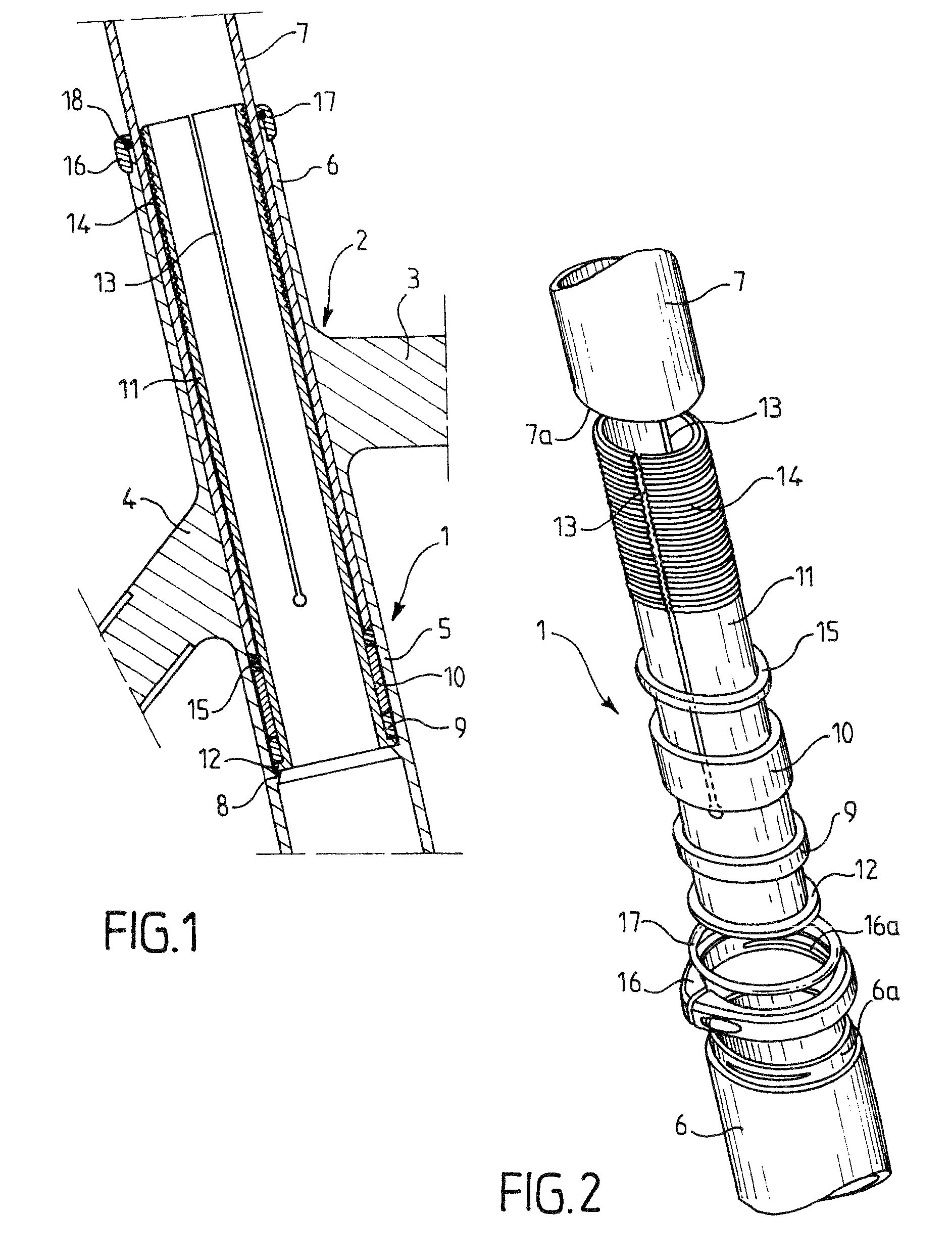
[0057]FIGS. 1 and 2 are partial views showing the portion of a bicycle frame in which a saddle post supporting device 1 according to the invention is integrated. This part of the bicycle frame can be designed as a saddle coupling node 2, in which an upper tube 3, braces of which one (4) is visible in FIG. 1, as well as a saddle tube 5 are brought together.

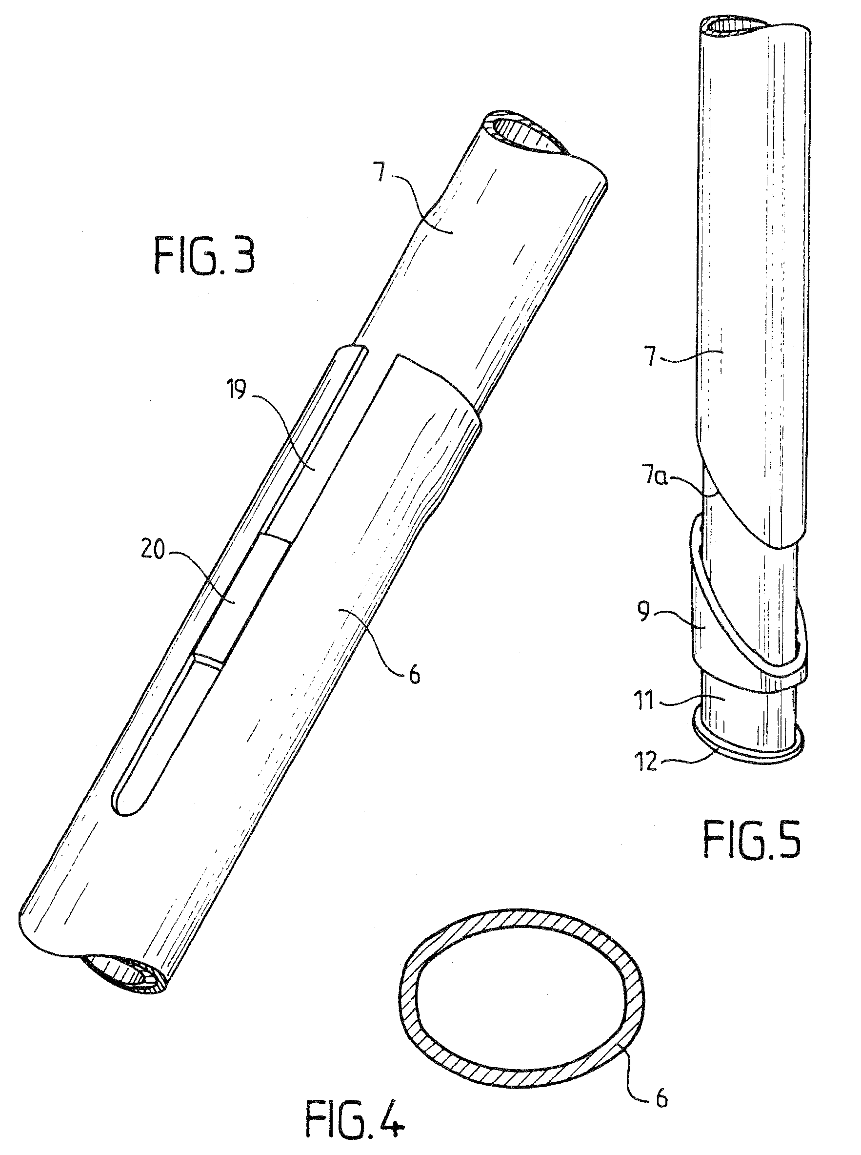
[0058]The upper part of the saddle tube 5 comprises a tubular saddle post fitting 6. In the illustrated example, the saddle post fitting 6 consists of the top end of the saddle tube 5 that is sized to accommodate a saddle post 7.

[0059]The means for holding the saddle post 7 in a longitudinal position that is determined relative to the tubular fitting 6 comprises a stop 8 (see FIG. 1).

[0060]In a first embodiment, the stop 8 is arranged on the inside wall of the fitting. This stop 8 is arranged so as to delimit the insertion length of the saddle post 7 in the fitting 6 by working with a stop surface 7a that in this first embodiment c...

second embodiment

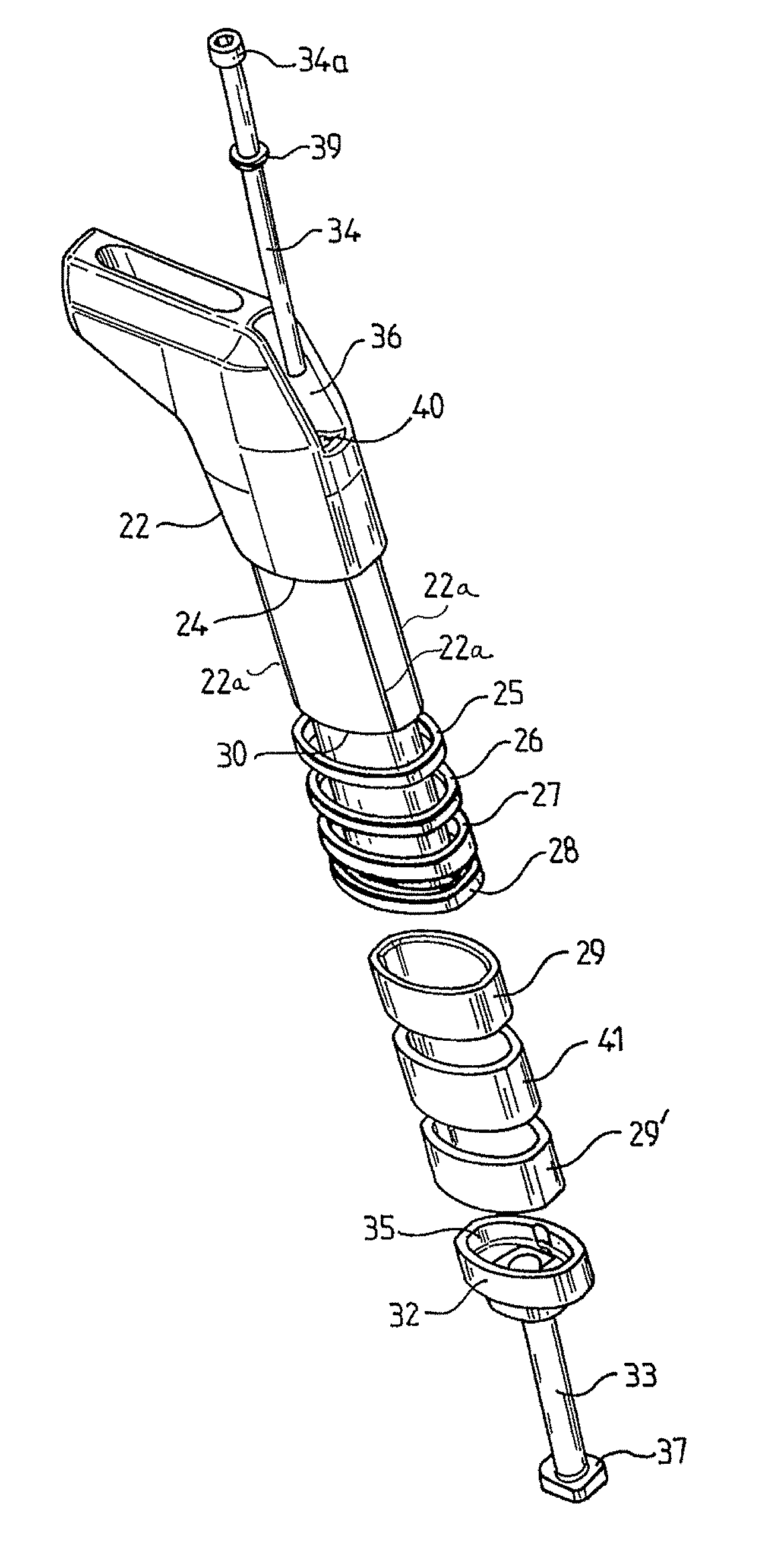
[0086]FIGS. 6 to 8 illustrate a saddle post supporting device 22 according to the invention.

[0087]As in the first embodiment, this supporting device 21 comprises a tubular fitting 6 (see FIG. 8) that consists of the top end of a saddle tube. The supporting device is able to accommodate a saddle post 22 and comprises means for locking the latter in rotation. These locking means can advantageously, as already mentioned, consist of the non-circular shape of the saddle post 22 and the saddle post fitting 6 whose inside wall has a shape that is complementary to that of the saddle post.

[0088]The saddle post supporting device 22 also comprises means of holding the saddle post 22 in a longitudinal position that is determined relative to the fitting of the saddle post 6. According to this second embodiment, the means of holding the post comprises a stop that consists of the end face 23 of the fitting 6 that is able to work with a stop surface on the saddle post 22. This stop surface consists...


PUM


Abstract

The device includes a tubular fitting (6) that is part of a bicycle frame and able to accommodate a saddle post (7), elements (19,20) for locking the saddle post (7) in rotation, and members (8) for holding the saddle post (7) in a longitudinal position that is determined relative to the tubular fitting (6). The holding members comprise a stop surface (7a) that is provided on the saddle post (7) and able to work with a stop (8) that is provided on the fitting (6) so as to delimit the insertion length of the saddle post (7) in the latter. The holding members also include at least one annular crosspiece (9, 10) that can be arranged between the stop surface and the stop so as to allow the adjustment of the insertion length.

Description

[0001]This invention relates to a saddle post supporting device, in particular for attaching a bicycle saddle to a bicycle frame.BACKGROUND OF THE INVENTION[0002]The attaching of a saddle to a bicycle frame is done using a saddle post that holds means for attaching the saddle to one of its ends, whereas its opposite end is suitable for working with a supporting device by being inserted into a tubular fitting of the latter.[0003]This fitting can consist directly of the top end of a saddle tube of the bicycle frame or a tubular element that is arranged in the saddle tube, in the intersection of the latter and the upper tube of the bicycle frame. The fitting has an inside dimension that is adapted to the outside dimension of the post so as to make it possible for the post to slide inside the fitting in the vertical direction to allow the vertical adjustment of the saddle relative to the crankset shaft for adaptation to the size of the bicyclist.[0004]The supporting device comprises mea...

Claims


Application Information

Patent Timeline
IPC IPC(8): B62J1/00B62J1/08
CPCB62K19/36
Inventor JULLIARD, ERICROUDERGUES, FREDERIC
Owner LOOK CYCLE INT
Why Eureka
Try Eureka