Extracting energy from flowing fluids

a technology of flowing fluids and energy, applied in water-power plants, climate sustainability, specific program execution arrangements, etc., can solve the problems of negative environmental impact, large and costly prime mover, and difficulty in harnessing energy, so as to increase the pressure drop across the prime mover

Inactive Publication Date: 2010-05-11
DAVIDSON AARON +1
View PDF6 Cites 46 Cited by
  • Summary
  • Abstract
  • Description
  • Claims
  • Application Information

AI Technical Summary

Benefits of technology

[0016]When applied to use in energy collection apparatus for extracting energy from a flowing liquid, the diffuser is typically positioned in a naturally occurring flow of water and a prime mover is positioned in or near the constriction. Preferably means are provided to sense the output of the prime mover and means are provided to adjust the aerofoil section members for example by pivoting the aerofoil section members about their pivot axes to adjust the size of the gaps or slots between the aerofoil section members in accordance with the sensed output such that the aerofoil section members can be moved to an optimum position where maximum output of the prime mover is achieved. Preferably flow sensing means are provided to sense the velocity of flow of fluid in the flow passage and the optimum position of the aerofoil section members to provide maximum output from the prime mover can be calibrated in accordance with the velocity of the flow of fluid through the flow passage.
[0019]Suitably the aerofoil section members are arranged in series between the inlet and outlet such that other than at the inlet and outlet, the trailing portion or edge of one aerofoil section member is adjacent the leading portion or edge of the immediately adjacent trailing aerofoil section member and a gap or slot is provided between a trailing portion or edge of each aerofoil section member and the leading portion or edge of the adjacent profiled section (apart from at the aerofoil section members at the leading and trailing end of the diffuser). The gaps or slots between the respective aerofoil section members allow the introduction of high energy fluid flow from outside of the diffuser into the flow passage whereby boundary layer separation is prevented so that the diffuser recovers some of the velocity head, thereby increasing the pressure drop across the prime mover and hence power output. As referred to above, the size of the gaps can be adjusted in accordance with the output of the prime mover so that the optimum position of the members can be set. Each aerofoil section member may be adjusted separately or all the aerofoil section member may be adjusted to the same extent. Preferably the aerofoil section members are mounted for pivotal movement about their longitudinal axes and means may be provided for selectively pivoting the aerofoil section members about their pivot axes. The adjusting means may be controlled by a programmable microcontroller to enable individual aerofoil section members to be pivoted about their axes either simultaneously to the same extent or separately. Thus the gaps or slots between respective adjacent aerofoil section members may be adjusted to the same extent or to a different extent. The velocity of the flow of fluid in the flow passage may also be monitored by the microcontroller such that the optimum position of the aerofoil section members can be set in accordance with the velocity of flow to provide optimum output from the prime mover.

Problems solved by technology

These systems whilst relatively efficient can negatively impact the environment during and following construction of the dams.
A slow moving body of fluid however requires a large and costly prime mover to generate the necessary motion to drive energy extraction means.
While the body of fluid may well be capable of providing substantial energy, it is the harnessing of that energy which is difficult.
The costs of systems currently proposed or in use are too high to justify their broad implementation.
In the various systems which are presently used, it is difficult to obtain a sufficiently high fluid velocity to enable efficient extraction of energy.

Method used


Image

  • Extracting energy from flowing fluids
  • Extracting energy from flowing fluids
  • Extracting energy from flowing fluids

Examples


Embodiment Construction

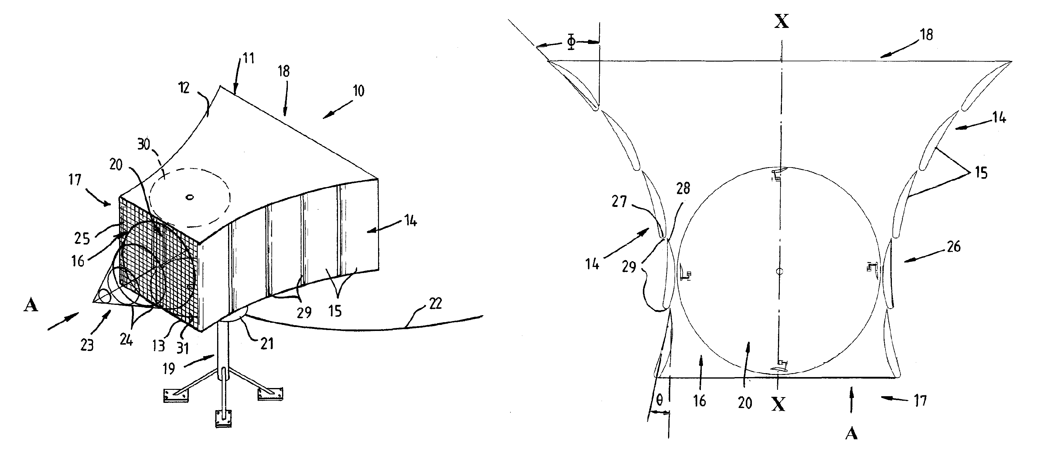
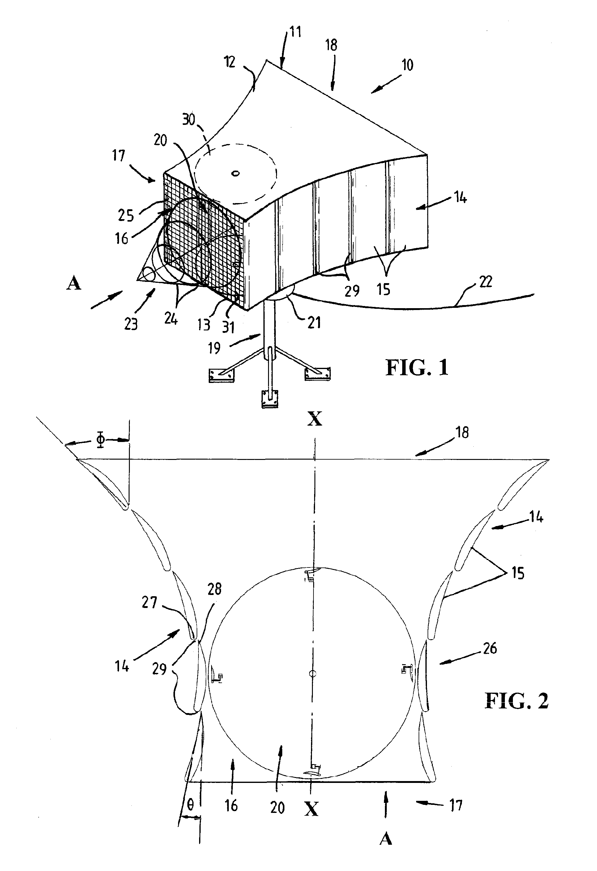
[0036]Referring firstly to FIG. 1, there is illustrated fluid energy extraction apparatus 10 according to an embodiment of the invention submerged within a flowing fluid for example within a river, the direction of flow of which is indicated by the arrow A. The apparatus 10 includes a diffuser 11 having top and bottom planar walls 12 and 13 and opposite side walls 14 defined by a plurality of linear aerofoil section members 15 of constant cross section which extend between the top and bottom walls 12 and 13 and which have their leading and trailing edges extending linearly and substantially at right angles to the planar walls 12 and 13. The diffuser 11 thus defines a flow passage 16 of substantially rectangular cross section but which varies in dimensions between a leading inlet 17 and trailing outlet 18 of the diffuser 11.

[0037]The diffuser 11 is mounted on a pedestal 19 for rotation about a substantially vertical axis such that the diffuser 11 may automatically adjust to the direc...


PUM


Abstract

A method and apparatus (10) for extracting energy from flowing fluids using a diffuser (11) which has side walls (14) formed from a series of aerofoil section members (15) with gaps (29) provided between the leading and trailing ends of the members (15) to allow introduction of fluid from outside of the diffuser (11) into the diffuser flow passage (16) such that increased energy can be extracted from the flowing fluid by a prime mover (20) located in the flow passage (16).

Description

TECHNICAL FIELD[0001]This invention relates a method and apparatus for extracting energy from flowing fluids and in particular to an improved method and apparatus for increasing the efficiency of extraction of energy from flowing liquids.BACKGROUND ART[0002]It is well known to extract energy from a flowing fluid by the use of suitable turbines which drive electrical generators to generate electricity. Such arrangements are commonly used in hydroelectric systems and usually use a head of water created through the construction of a dam to create a flow of water through conduits in which turbines are positioned. These systems whilst relatively efficient can negatively impact the environment during and following construction of the dams.[0003]Other systems have been proposed and used which use the sea as a source of energy. Energy can be extracted from the sea by using the wave motion of the sea or tidal movement of the sea. A slow moving body of fluid however requires a large and costl...

Claims


Application Information

Patent Timeline
Patent Type & Authority Patents(United States)
IPC IPC(8): F04D27/02E02B9/08F03B3/18F03B13/26F03D1/04F03D3/04
CPCF03B3/183F03D1/04F03D3/0418F05B2210/18F05B2240/133Y02E10/38Y02E10/72Y02E10/223Y02E10/74Y10S415/907Y02E10/28Y02E10/20Y02E10/30
Inventor DAVIDSON, AARONHILL, CRAIG COLIN
Owner DAVIDSON AARON
Why Eureka
Try Eureka