
Turbine blade with spar and shell construction

Inactive Publication Date: 2010-05-11
FLORIDA TURBINE TECH
View PDF16 Cites 26 Cited by
  • Summary
  • Abstract
  • Description
  • Claims
  • Application Information

AI Technical Summary

Benefits of technology

[0012]The present invention is a turbine blade having a spar and shell construction, in which the spar includes a dove-tail that fits within a two piece platform and root assembly having a fir-tree configuration that slides into a dove-tail slot of the rotor disk. The two piece platform assembly includes the blade platforms to form the gas flow path, and is secured together by a clamping screw or other fastener to facilitate installation of the blade assembly into the rotor disk. The spar and the platform halves each include cooling air passages to supply cooling air to th

Problems solved by technology

This construction is considered to be very weak in holding the blade together during operating speeds producing high centrifugal forces that tend to pull the spar away from the fir-tree root or base.
Also, this construction does not permit removal and replacement of the shell component, which is known to be the life limiting part of the spar and shell constructed blade.

Method used


Image

  • Turbine blade with spar and shell construction
  • Turbine blade with spar and shell construction
  • Turbine blade with spar and shell construction

Examples


Embodiment Construction

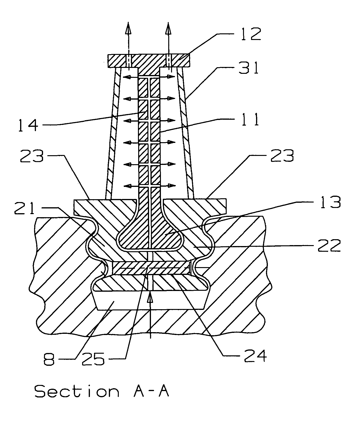
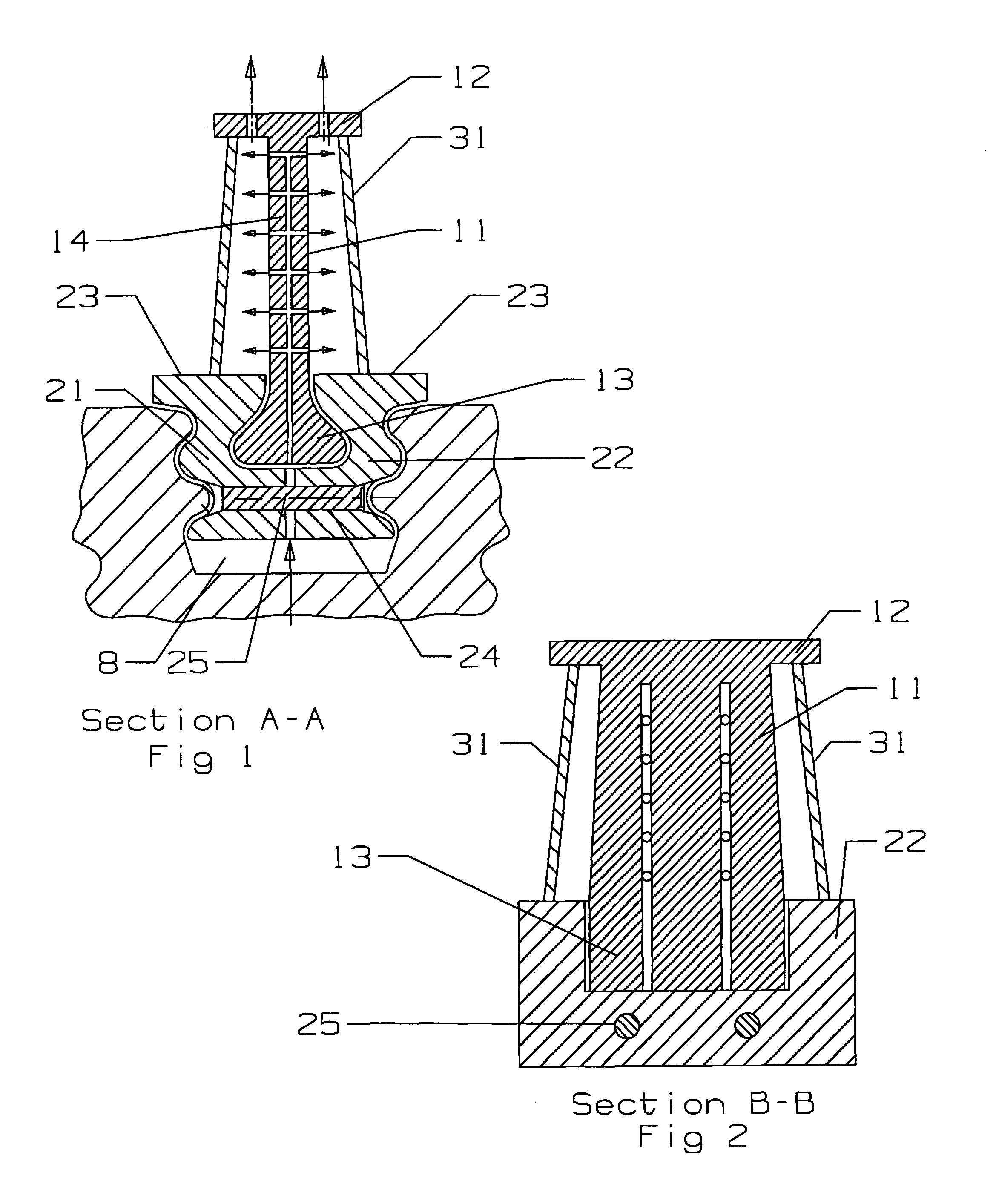
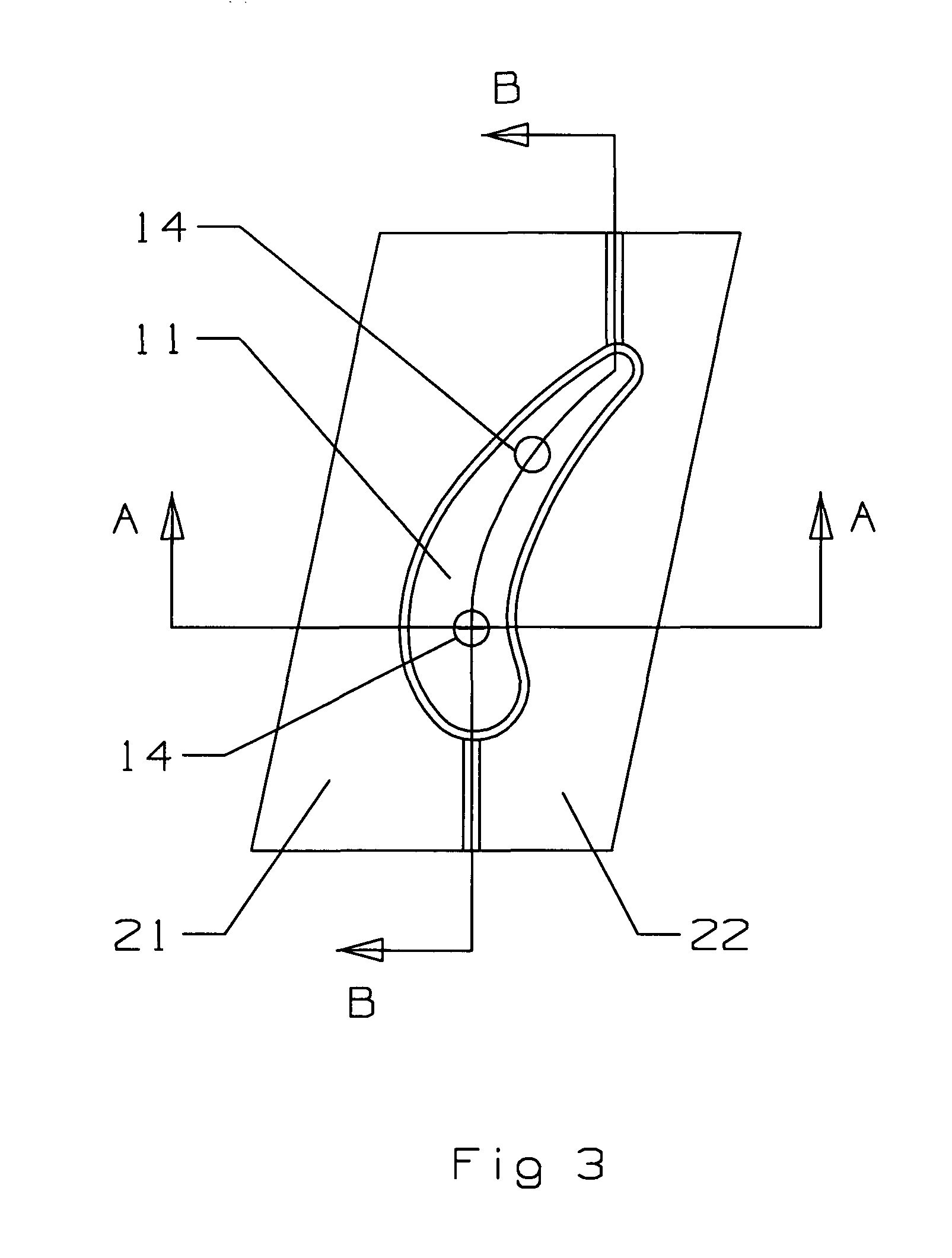
[0016]The present invention is shown schematically in FIG. 1 and is a turbine blade made from a spar and shell construction having a fir-tree root and platform that will slide into an attachment slot of a rotor disk. The turbine blade includes a spar 11 with a blade tip 12 and a dove-tail 13 having a tear-drop shape on the opposite end from the tip. The spar 11 includes one or more cooling air passages 14 to channel cooling air from the root to portions of the blade for cooling. The fir-tree root and platform of the blade assembly includes two platform halves 21 and 22 that, when combined, form a fir-tree configuration that can slide within the attachment slot formed in the rotor disk. Each platform halve 21 and 22 includes a slot 26 that, when joined together, form a slot that can secure the dove-tail 13 of the spar 11 to the platform halves. The spar dove-tail and the platform halves slots 26 are of such size and shape to secure the spar 11 to the dove-tail configuration of the pl...


PUM


Abstract

A turbine blade with a spar and shell construction in which the spar includes a blade tip and a dove-tail on the root end of the spar. A pair of platform halves form a fir-tree attachment capable of sliding into an attachment slot formed within a rotor disk. The platform halves form a slot within the fir-tree configuration that will pinch the dovetail slot of the spar and secure the spar to the platform halves against radial displacement. The shell is secured between the spar tip and the platform of the platform halves when assembled together. The spar includes cooling air passages and impingement cooling holes to provide backside impingement cooling of the shell. A fastener secures the two platform halves together so that the spar and shell blade assembly can slide into the attachment slot within the rotor disk.

Description

CROSS-REFERENCE TO RELATED APPLICATIONS[0001]This application is related to U.S. patent application Ser. No. 11 / 243,308 filed on Oct. 4, 2005 by Wilson et al and entitled TURBINE VANE WITH SPAR AND SHELL CONSTRUCTION.BACKGROUND OF THE INVENTION[0002]1. Field of the Invention[0003]The present invention relates generally to fluid reaction surfaces, and more specifically to a turbine blade with a spar and shell construction.[0004]2. Description of the Related Art Including Information Disclosed Under 37 CFR 1.97 and 1.98[0005]In a gas turbine engine, such as an aero engine used to power an aircraft or an industrial gas turbine engine used to produce electrical power, a turbine section includes a plurality of stages of rotor blades and stator vanes to extract the energy from the hot gas flow passing through. The engine efficiency can be improved by increasing the temperature of the hot gas flow entering the turbine. However, the inlet temperature is limited to the material properties of...

Claims


Application Information

Patent Timeline
IPC IPC(8): F01D5/14F04D29/34
CPCF01D5/025F01D5/147F01D5/14F01D5/028
Inventor DAVIES, DANIEL O.
Owner FLORIDA TURBINE TECH
Learn More