Methods and system for controlling an illuminating apparatus

a technology of illumination apparatus and control system, which is applied in the direction of electric variable regulation, process and machine control, instruments, etc., can solve the problems of inability to achieve the effect of reducing power consumption by changing luminance more smoothly with the change of luminous intensity of circumstances, and limited selection of luminance levels while the corresponding cost increases, so as to achieve digital luminance control, reduce power consumption, and control the luminance of the illuminated area

Active Publication Date: 2010-05-11
SIGNIFY HLDG BV
View PDF15 Cites 32 Cited by
  • Summary
  • Abstract
  • Description
  • Claims
  • Application Information

AI Technical Summary

Benefits of technology

[0007]The present invention provides an improved digital luminance controlling system, in a light source controlling apparatus thereof, the resistor and the luminaries are connected by a switch, thus the luminance of the illuminated area could be controlled by selecting the number of the ignited luminaries. By reducing the number of the ignited luminaries, the power consumption could be reduced.
[0008]The present invention further provides an improved digital luminance controlling system, and a digital luminance controlling apparatus thereof compares two successively detected values of the luminous intensity of the circumstance. If the difference between the values is smaller than a predetermined value, the sampling frequency is decreased, and if the difference is greater than another predetermined value, the sampling frequency is increased. By adjusting the sampling frequency timely, the luminance controlling system could operate less frequently and thereby the power consumption could be reduced.
[0009]The present invention further provides an analog luminance controlling system, comprising a light sensing apparatus, an analog luminance controlling apparatus and a group of light sources. When the light sensing apparatus detects the luminous intensity of the circumstance, it sends an signal of the luminous intensity of the circumstance to the analog luminance controlling apparatus, and the signal of the luminous intensity of the circumstance is converted into luminance controlling signal according to a preset magnification by the analog luminance controlling apparatus, and the controlling signal is applied to the light source in the form of current or voltage to adjust the luminance of the light source. Since the luminance controlling apparatus works in an analog manner, real-time luminance adjustment could be realized, and thus the power consumption is reduced. Meanwhile, since the analog-to-digital converter (ADC), the digital signal processor (DSP), the memory and the light source controlling apparatus are not needed any more, the objects of saving costs and further reducing power consumption can be achieved.

Problems solved by technology

Since the number of luminance levels in the prior art is limited by the number of the selection switches, with the increasing of luminance levels, the number of selection switches and the number of the groups of the resistors increase simultaneously, thus the selection of the number of luminance levels is obviously limited while the corresponding cost increases.
Therefore, the object of reducing power consumption by changing the luminance more smoothly with the change of the luminous intensity of the circumstance cannot be achieved.

Method used


Image

  • Methods and system for controlling an illuminating apparatus
  • Methods and system for controlling an illuminating apparatus
  • Methods and system for controlling an illuminating apparatus

Examples


Embodiment Construction

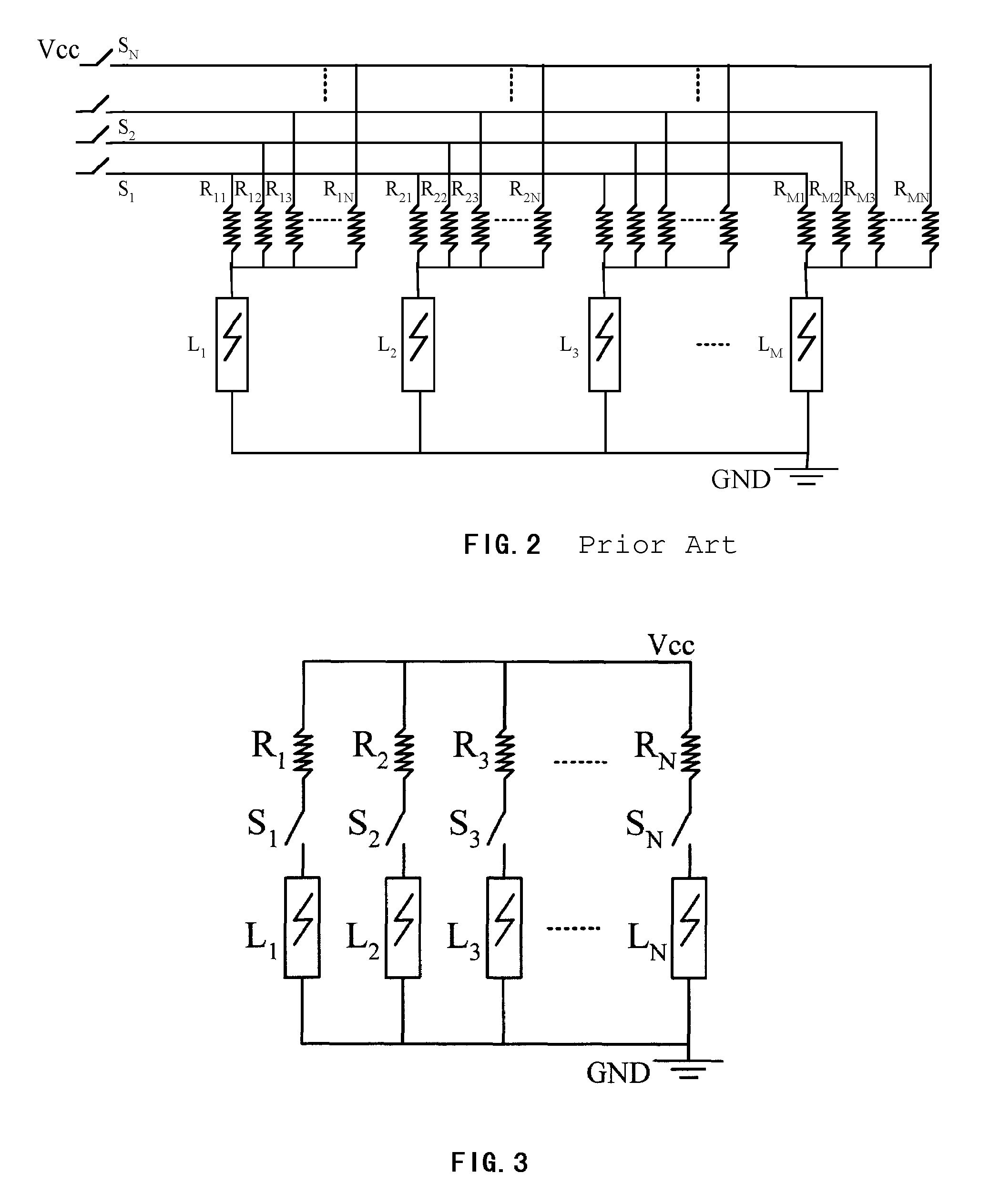
[0022]FIG. 3 is the digital luminance controlling apparatus of an embodiment of the present invention. In the figure, a group of selection switches (S1, S2, . . . , SN) is connected between the resistors (R1, R2, . . . , RN) and the luminaries (L1, L2, . . . , LN) that compose the illuminating apparatus, and a corresponding number of luminaries can be set to the ignited state by setting different numbers of switches to the connection state, and thereby to make the light source comprising the group of luminaries provide the desired luminance in the illuminated area. Compared with the prior art technical solution as shown in FIG. 2, the embodiment could greatly reduce the number of resistors needed and the complexity of the circuits while maintaining the same luminance controlling level, thus the power consumption is reduced.

[0023]FIG. 4 is the schematic plan view of a group of luminaries composing the illuminating apparatus of an embodiment of the present invention. In the area that ...


PUM


Abstract

This invention provides an improved digital luminance controlling system, which can control the luminous intensity of an illuminating apparatus by choosing the number of the ignited luminaries. It optimizes the number of the ignited luminaries according to the different contribution rate of each luminary to the general luminous intensity to reduce the power consumption. By properly adjusting the sampling frequency of the luminous intensity of the circumstance, this invention could decrease the operating frequency of the luminance controlling system, thereby to further reduce the power consumption. This invention also provides a analog type of the luminance controlling system, which consists of a optical sensing apparatus, a analog type of the luminance controlling apparatus and a set of optical source and can realize a real time luminance adjustment, to reduce the power consumption.

Description

FIELD OF THE INVENTION[0001]The present invention relates to a luminance controlling system, particularly to an adaptive system that could automatically adjust its own luminous intensity according to the luminous intensity of a circumstance. As used herein, the term “circumstance” refers to ambient light as sensed by the system.BACKGROUND OF THE INVENTION[0002]Electronic devices such as mobile phone, PDA (Personal Digital Assistant), pager, etc. usually have a display screen, which is mostly a liquid crystal displaying apparatus that could make the content to be displayed visible by providing backlights when the luminous intensity of the circumstance is not high enough. Meanwhile, these electronic devices such as mobile phone and PDA (Personal Digital Assistant) may also have a data inputting apparatus comprising a set of keys, and the devices make the keypad visible through backlights when the luminous intensity of the circumstance is not high enough.[0003]FIG. 1 is the prior art d...

Claims


Application Information

Patent Timeline
Patent Type & Authority Patents(United States)
IPC IPC(8): H05B37/00G09G3/20G09G3/34
CPCG09G3/3426G09G2360/144G09G2330/021G09G2320/0626
Inventor QIAN, XUECHENG
Owner SIGNIFY HLDG BV
Why Eureka
Try Eureka