Light source apparatus and light source adjusting module

a technology of light source apparatus and light source, applied in the direction of electric variable regulation, process and machine control, instruments, etc., can solve the problems of short lifetime and high temperature, inability to detect the conducting phase information, and high power consumption, so as to save fabrication costs and avoid the use of extra pins

Active Publication Date: 2009-12-24
NOVATEK MICROELECTRONICS CORP
View PDF7 Cites 3 Cited by
  • Summary
  • Abstract
  • Description
  • Claims
  • Application Information

AI Technical Summary

Benefits of technology

[0009]The present invention is directed to a light source apparatus and a light source adjusting module, by which a compatibility problem can by effectively resolved, and utilization of extra pins can be avoided, so as to save a fabrication cost.

Problems solved by technology

Though the halogen lamp has an advantage of high luminance, it also has disadvantages of high power consumption, short lifetime and high temperature, etc.
However, the conventional driver 250 cannot detect the conducting phase information of the AC voltage signal modulated by the phase modulator 220.
However, such structure is different to the MR16 lamp apparatus specification (since the pins required for connecting the variable resistor are added), so that the original MR16 lamp apparatus specification cannot be directly applied to the LED 260, and therefore utilization thereof is inconvenient.

Method used


Image

  • Light source apparatus and light source adjusting module
  • Light source apparatus and light source adjusting module
  • Light source apparatus and light source adjusting module

Examples


Embodiment Construction

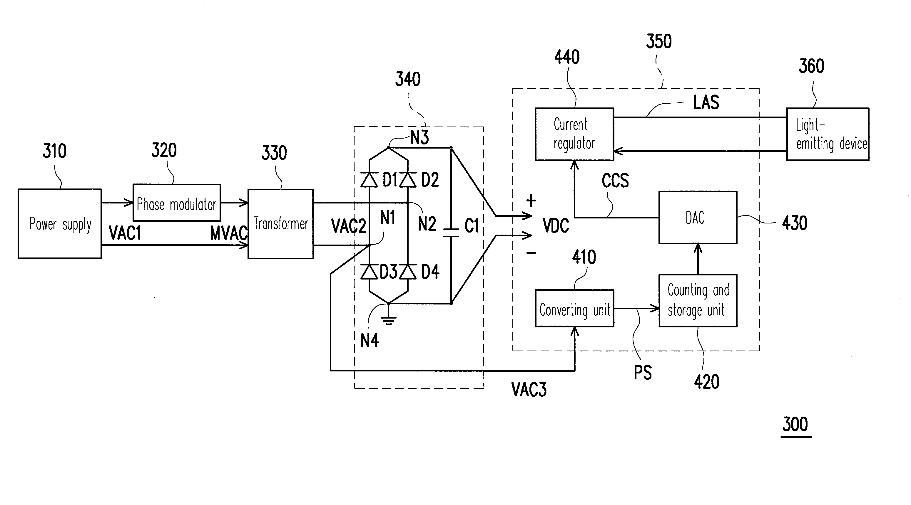
[0027]FIG. 3 is a block diagram illustrating a light source apparatus according to an embodiment of the present invention. Referring to FIG. 3, the light source apparatus 300 includes a power supply 310, a phase modulator 320, an electrical transformer 330, a rectifier 340, a light source adjusting module 350 and a light-emitting device 360. The power supply 310 provides an AC voltage signal VAC1, for example, an 110V AC voltage signal. The phase modulator 320 is coupled to the power supply 310 for receiving the AC voltage signal VAC1 and modulating a conducting phase of the AC voltage signal VAC1 to generate a modulated AC voltage signal MVAC. Wherein, the modulated AC voltage signal MVAC can serve as a basis for adjusting a luminance of the light-emitting device 360.

[0028]The electrical transformer 330 is coupled to the phase modulator 320 for receiving and transforming the modulated AC voltage signal MVAC, so as to generate an AC voltage signal VAC2. In the present embodiment, fo...


PUM


Abstract

A light source apparatus and a light source adjusting module are provided. The light source apparatus includes a power supply, a phase modulator, an electrical transformer, a light source adjusting module and a light-emitting device. The power supply provides a first AC voltage signal. The phase modulator receives the first AC voltage signal and adjusts a conducting phase of the first AC voltage signal to generate a modulated AC voltage signal. The electrical transformer transforms the modulated AC voltage signal to generate a second AC voltage signal. The light adjusting module generates a luminance adjusting signal according to a state of the second AC voltage signal. The light-emitting device receives the luminance adjusting signal to generate a corresponding light source.

Description

CROSS-REFERENCE TO RELATED APPLICATION[0001]This application claims the priority benefit of Taiwan application serial no. 97122864, filed on Jun. 19, 2008. The entirety of the above-mentioned patent application is hereby incorporated by reference herein and made a part of specification.BACKGROUND OF THE INVENTION[0002]1. Field of the Invention[0003]The present invention relates to a light source adjusting technique. More particularly, the present invention relates to a light source apparatus and a light source adjusting module.[0004]2. Description of Related Art[0005]FIG. 1 is a block diagram illustrating a light-emitting device applying a MR16 halogen lamp. Referring to FIG. 1, a power supply 110 provides an alternating current (AC) voltage signal (for example an 110V AC voltage signal). Next, a phase modulator 120 modulates a conducting phase of the AC voltage signal. An electrical transformer 130 transforms the modulated 110V AC voltage signal to the 12V or 24V AC voltage signal ...

Claims


Application Information

Patent Timeline
Patent Type & Authority Applications(United States)
IPC IPC(8): H05B37/02
CPCH05B33/0845H05B45/10
Inventor LIU, YI-TEYEN, CHIH-JENHSIEH, CHIH-YUANCHENG, LAN-SHAN
Owner NOVATEK MICROELECTRONICS CORP
Why Eureka
Try Eureka