
Automatic lighting control system

a technology of automatic lighting control and control system, which is applied in the direction of traffic control system, transportation and packaging, instruments, etc., can solve the problems of frequent malfunction, inability to control the lamp in response to motion of a person or a vehicle, and inefficiency in cost, so as to improve the comfort of movement and emotional satisfaction of residents, simplify the configuration of lamps and control the luminance of lamps.

Active Publication Date: 2013-07-02
BEST DIGITAL CO LTD
View PDF6 Cites 3 Cited by
  • Summary
  • Abstract
  • Description
  • Claims
  • Application Information

AI Technical Summary

Benefits of technology

[0011]Accordingly, it is an object of the present invention to reduce power consumption by simplifying configuration of lamps and controlling luminance of lamps on a resident or vehicle movement route by predicting motion of the resident or the vehicle through centralized control for a plurality of lamps, and to prevent accidents in dark regions by minimizing a control delay of lamps located on a movement route due to a calculating process such as sensor or motion detection.
[0012]It is another object of the present invention to provide increased movement convenience and emotional satisfaction of a resident or a user by securing a field of view on a movement route through lighting control having a route guidance function for the resident or the user.
[0013]It is still another object of the present invention to provide easy access to an intended resident building to a visitor who visits the resident building for the first time by a central server predicting a movement route of the visitor through mutual communication between the resident and the visitor and controlling lamps located on the predicted movement route to show the visitor the movement route.

Problems solved by technology

However, the lamp having such a sensor and a controller has problems that it is considerably expensive, which may result in inefficiency in terms of cost when many lamps are installed in a wide place such as the underground parking lot, and it is operated based on the sensor, which may result in its frequent malfunction.
These conventional models take considerable time to perform a procedure from calculation for real time motion detection through an image obtained through a camera to lamp control after motion check through the calculation, which may result in difficulty in lamp control in immediate response to motion of a person or vehicle.
Accordingly, these conventional models have problems of decreased efficiency due to frequent lamp adjustment after the person or vehicle passed by and increased risk of accident due to improper response of lamps.

Method used


Image

  • Automatic lighting control system
  • Automatic lighting control system
  • Automatic lighting control system

Examples


Embodiment Construction

[0041]Hereinafter, an automatic lighting control system according to a preferred embodiment of the present invention will be described in detail with reference to the accompanying drawings.

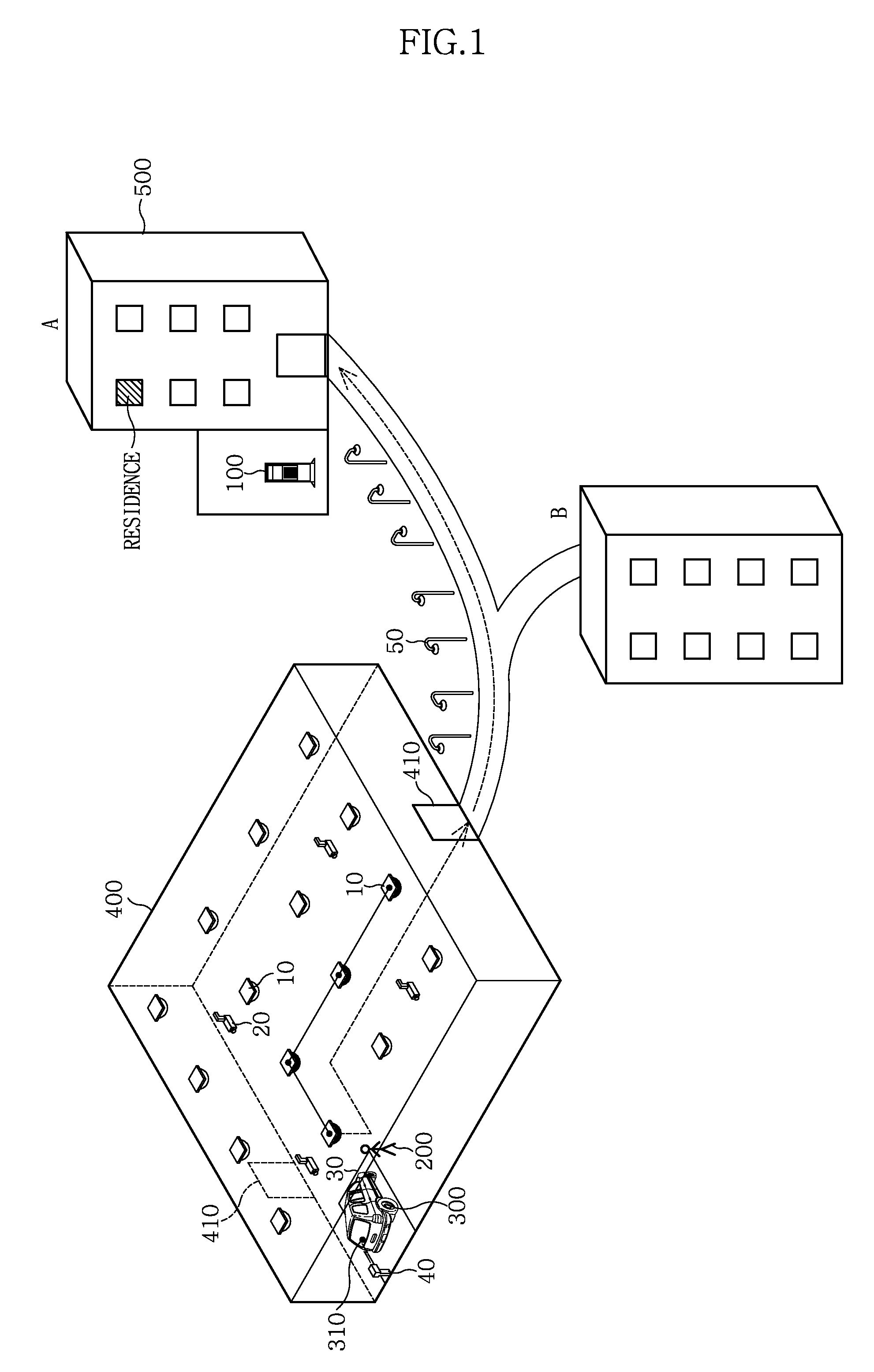
[0042]The present invention relates to control of lamps installed in an underground parking lot or a sidewalk affiliated with a complex building and / or lamps installed in corridors and stairs in the complex building, which is capable of predicting a movement route of a resident and turning on lamps corresponding to the predicted movement route, thereby providing the resident with movement convenience and emotional satisfaction and providing guide information to allow a visitor to visit a visit destination easily.

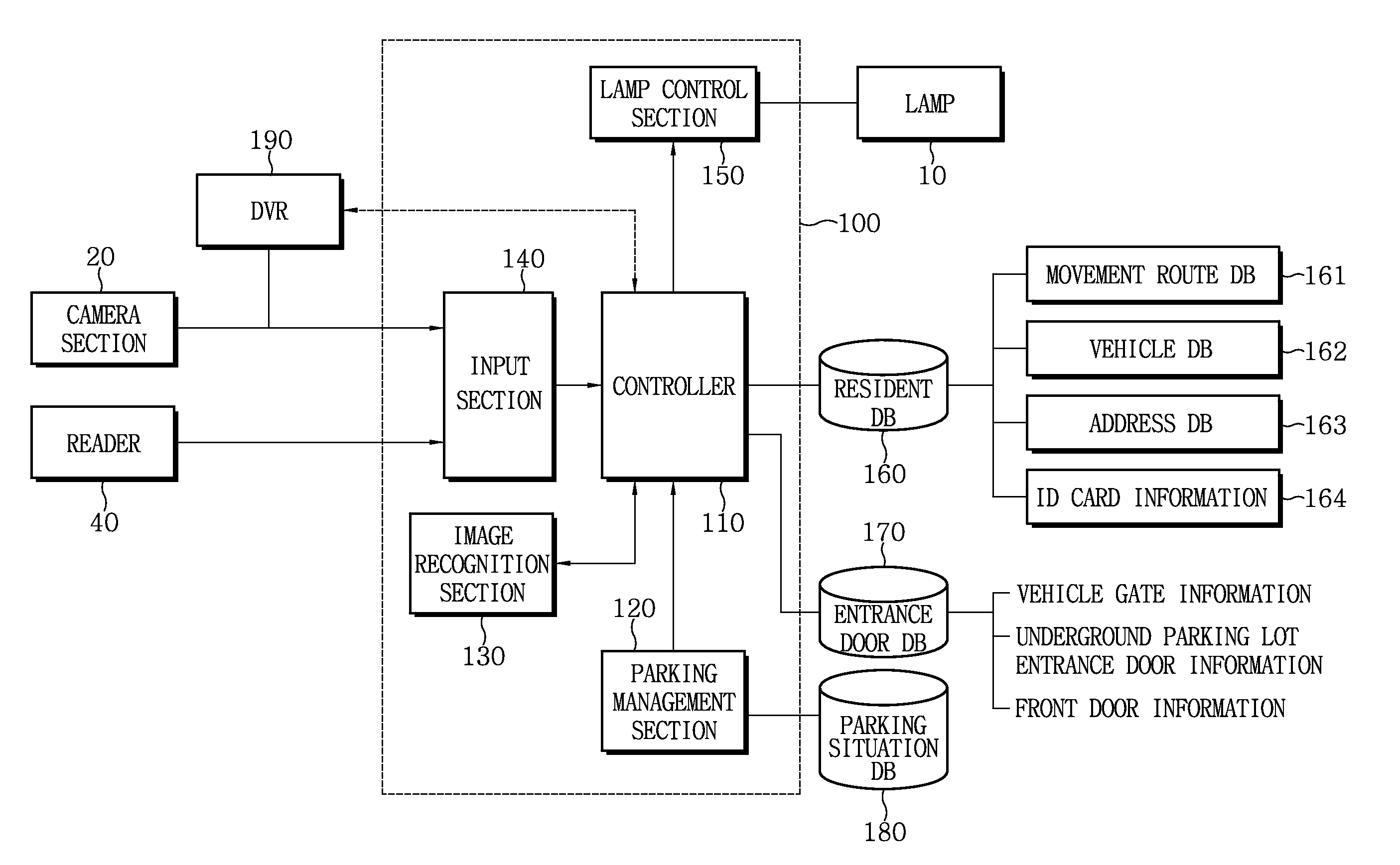
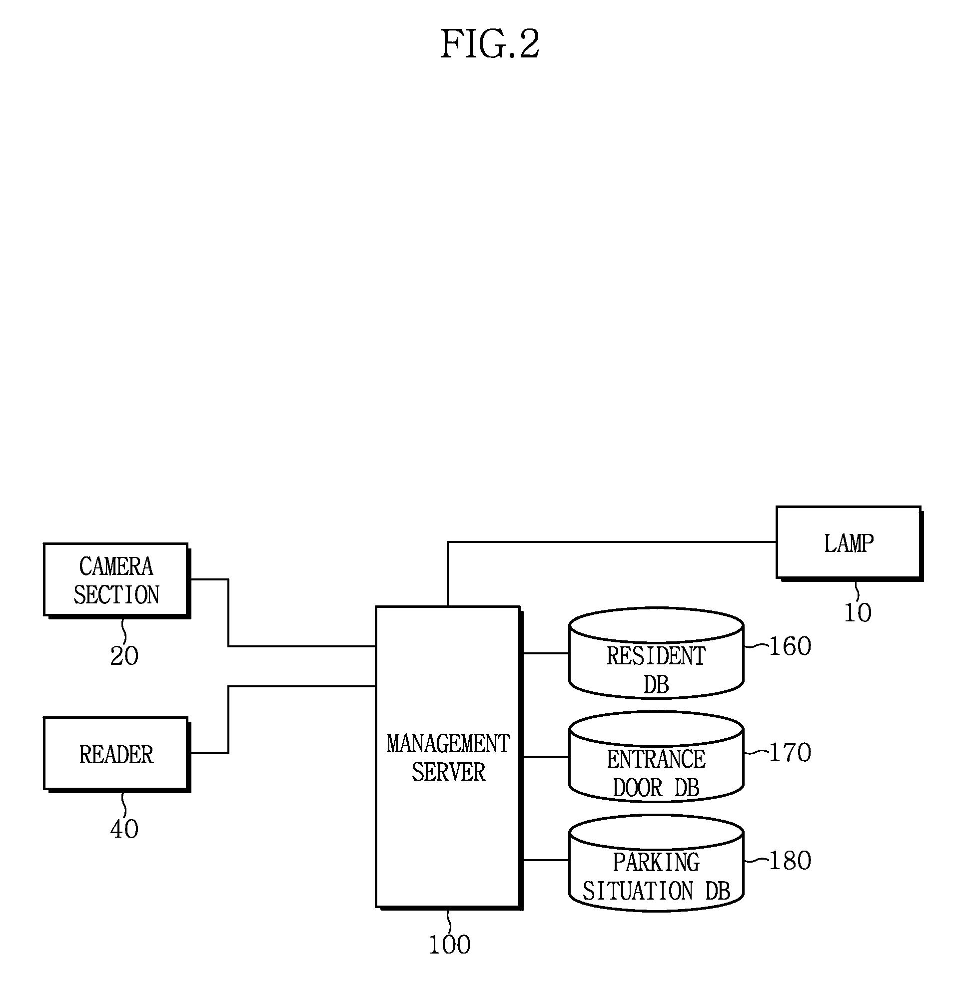
[0043]Referring first to FIG. 1 showing a structure of an automatic lighting control system according to an embodiment of the present invention, a management server 100 located in an administration center 510 of a complex building 500 may be connected, via a network, to lamps 10, cameras 2...


PUM


Abstract

The present invention relates to an automatic lighting control system, and more particularly, to an automatic lighting control system which is capable of predicting a movement route of a resident in a complex building and automatically controlling lighting located in the movement route. According to the present invention, it is possible to reduce power consumption by simplifying configuration of lamps and controlling luminance of lamps on a resident or vehicle movement route by predicting motion of the resident or the vehicle through centralized control for a plurality of lamps, and to provide increased movement convenience and emotional satisfaction of a resident by showing the resident a movement route through lamps and securing a field of view on the movement route.

Description

CROSS-REFERENCE TO RELATED APPLICATION[0001]This application claims the benefit of Korean Application No. 10-2010-0021870, filed on Mar. 11, 2010, with the Korean Intellectual Property Office, the disclosure of which is incorporated herein by reference.BACKGROUND OF THE INVENTION[0002]1. Field of the Invention[0003]The present invention relates to an automatic lighting control system, and more particularly, to an automatic lighting control system which is capable of predicting a movement route of a resident in a complex building and automatically controlling lighting located in the movement route.[0004]2. Description of the Related Art[0005]In general, complex buildings (such as apartments, villas, efficiency apartments, venture towers, etc.) have lamps, such as incandescent lamps, fluorescent lamps, LED lamps and the like, installed in underground parking lots, around sidewalks leading to entrance doors of the complex buildings, or in even corridors in the complex buildings.[0006]A...

Claims


Application Information

Patent Timeline
Patent Type & Authority Patents(United States)
IPC IPC(8): H05B37/02B60Q1/48G08G1/01
CPCH05B37/0227H05B47/125Y02B20/40
Inventor PARK, YOUNG SUKLEE, WON KYUNG
Owner BEST DIGITAL CO LTD
Learn More