Hysteretic switching regulator

a hysteretic switching and regulator technology, applied in the direction of power conversion systems, instruments, dc-dc conversion, etc., can solve the problems of inability to accurately predict the value of the equivalent series resistor (esr) in the tantalum capacitor suitable for use in the switching regulator, the cost of such discrete components is high, and the value of esr is too small to be utilized. achieve the effect of better understanding and prediction

Inactive Publication Date: 2010-05-11
PANASONIC SEMICON SOLUTIONS CO LTD
View PDF52 Cites 24 Cited by
  • Summary
  • Abstract
  • Description
  • Claims
  • Application Information

AI Technical Summary

Benefits of technology

[0013]The hysteretic switching regulator of the present invention provides numerous advantages over the prior art. One advantage is that because the control signal is generated so as to be substantially independent of the magnitude of the load current, the switching frequency of the regulator does not significantly vary in accordance with changes in load current. Another advantage associated with the present invention is that it exhibits improved response times when there are changes in the load or changes in the set point reference voltage. Yet another advantage of the present invention is that it minimizes switching losses and improves efficiency, especially at small load currents. One other advantage is that determining the best choice of values for the components of the device of the present invention is easier and requires fewer compromises due to less interaction between component values.

Problems solved by technology

Another problem with the switching regulator of FIG. 1a is that it is difficult to specify or even accurately predict the value of the equivalent series resistor (ESR) in the tantalum capacitors suitable for use in switching regulators.
It is noted that ceramic dielectric capacitors have too small a value of ESR to be utilized, as the resulting ripple signal is too small.
The use of such discrete components, which are costly, is undesirable for various reasons.
However, due to the current sense resistor 19, the DC voltage at the load 17 does not equal the DC voltage at the sampling point for generating the control signal, and therefore an error is introduced into the control signal, which causes an error in the regulated output voltage, VOUT.
However, such a configuration degrades the transient response of the switching regulator.
While the configuration illustrated in FIG. 3 helps reduce the error in VOUT associated with the series resistance, Rs, in the switching regulator configuration of FIG. 2, as more components are required, including energy storage elements (i.e., inductors and capacitors), the switching regulator of FIG. 3 exhibits a poor transient response and becomes prohibitively costly, because the required component values cannot be easily implemented within an integrated circuit.
Another problem with all of the foregoing prior switching regulator circuits, which utilize inductor current to generate the triangular control signal for the comparator, is that the amplitude of the triangular signal varies with the magnitude of the load current and this causes changes in the regulator switching frequency which may be unacceptably large when the inductor and load current vary over a wide range.
Other types of output filters have been proposed for generating the triangular control signal from the load voltage and inductor current, but they all have similar limitations as described above, as well as requiring several physically large R and C components that are not feasibly implemented in an integrated circuit.

Method used


Image

  • Hysteretic switching regulator
  • Hysteretic switching regulator
  • Hysteretic switching regulator

Examples


Embodiment Construction

[0024]The present invention now will be described more fully hereinafter with reference to the accompanying drawings, in which preferred embodiments of the invention are shown. This invention may, however, be embodied in many different forms and should not be construed as limited to the embodiments set forth herein: rather, these embodiments are provided so that this disclosure will be thorough and complete, and will fully convey the scope of the invention to those skilled in the art; like numbers refer to like elements throughout.

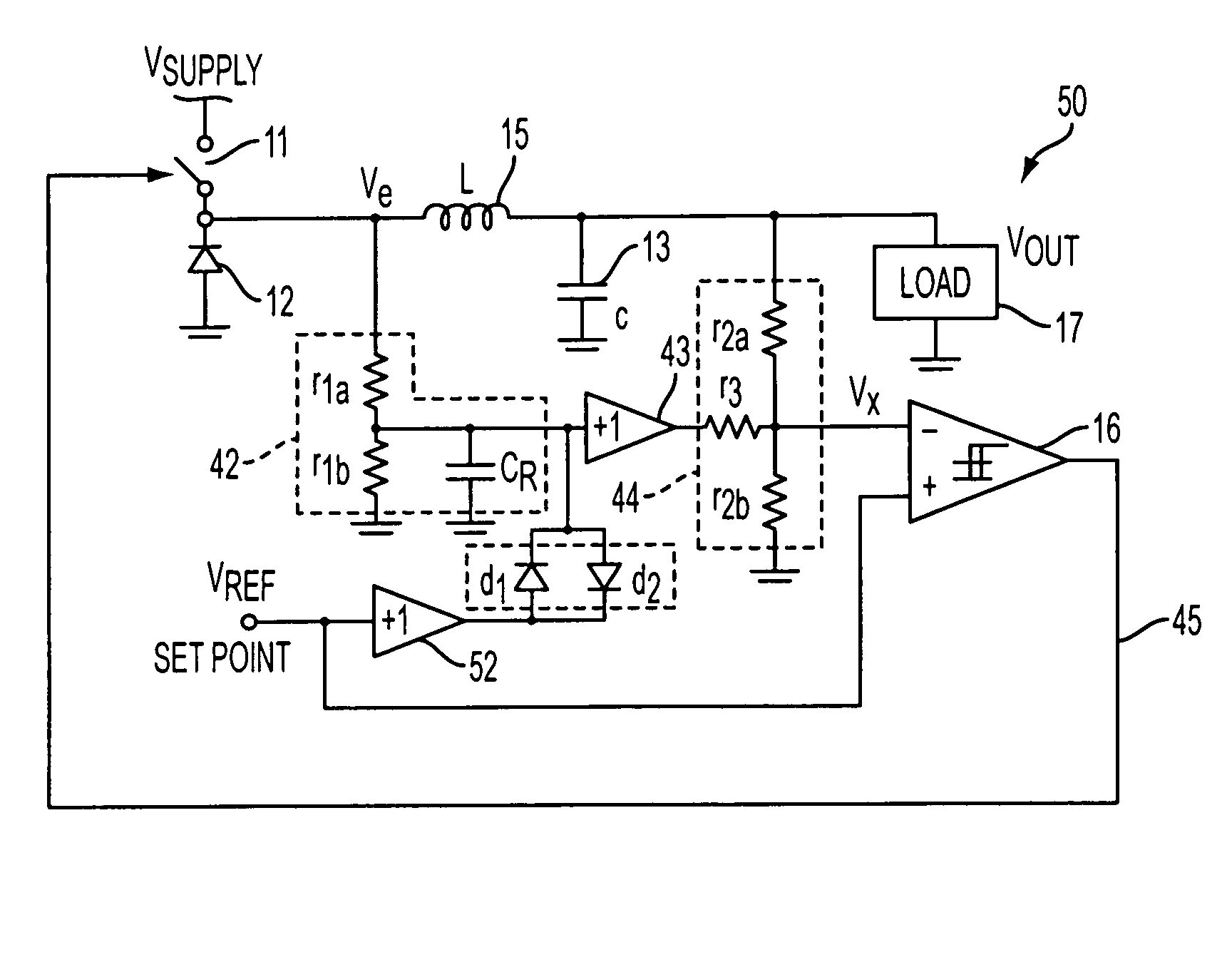
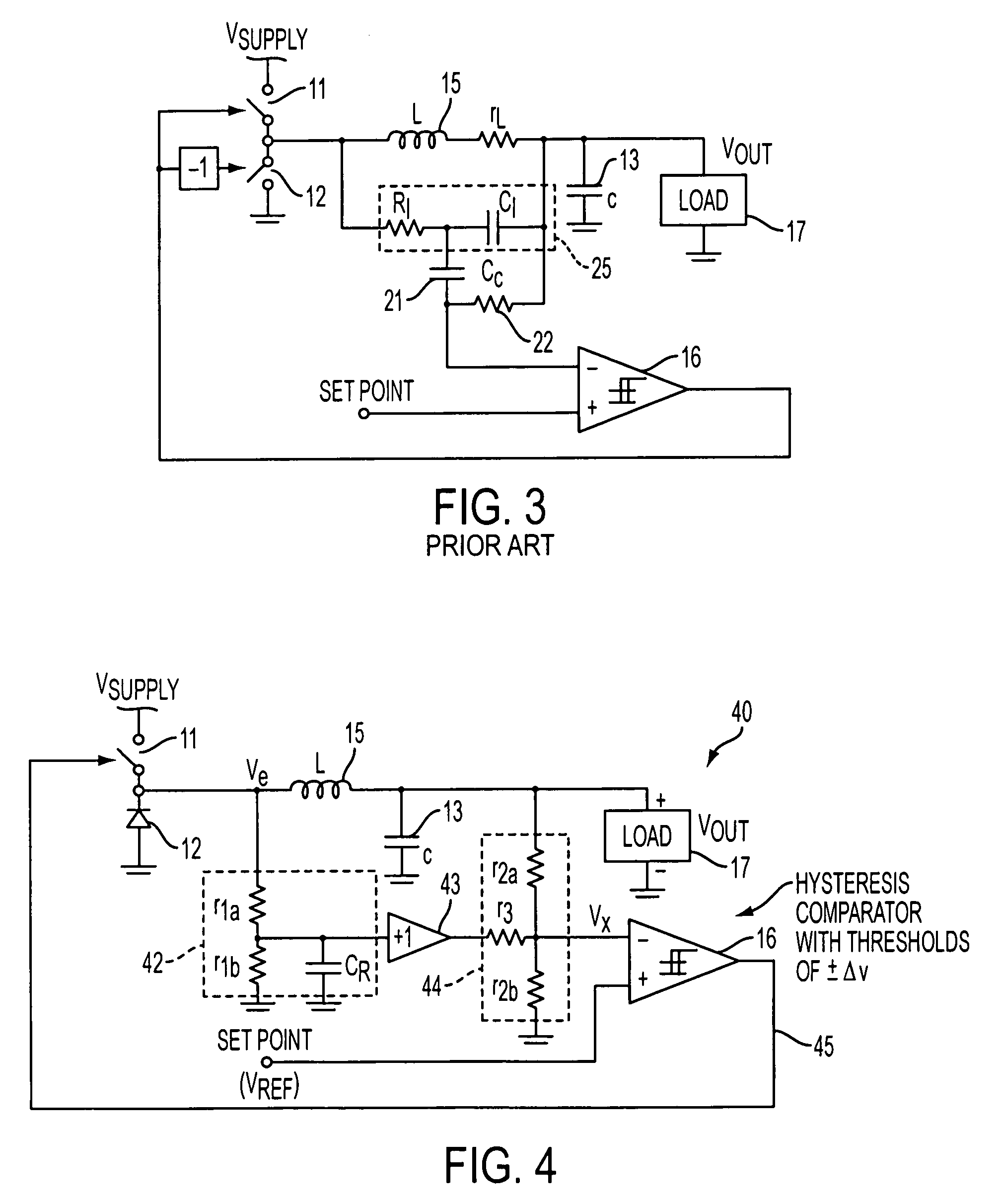
[0025]FIG. 4 illustrates an exemplary embodiment of a hysteretic switching regulator in accordance with the present invention. Referring to FIG. 4, the hysteretic switching regulator 40 includes a high-side switch 11 and a low-side switch 12 (which in the given embodiment is implemented by a diode, preferably an active diode, such as disclosed in U.S. patent application Ser. No. 11 / 094,369 filed on Mar. 31, 2005, which is hereby incorporated by reference i...


PUM


Abstract

A switching regulator circuit including a high-side switch and a low-side switch; an inductor having a first terminal coupled to a common terminal between the high-side switch and the low-side switch, and a second terminal coupled to an output terminal of the switching regulator circuit; a low-pass filter coupled to the first terminal of the inductor, where the low-pass filter is operative for generating a ramp signal based on the voltage signal present at the first terminal of the inductor; and a hysteretic comparator coupled to the low pass filter, where the hysteretic comparator receives the ramp signal as an input signal, and generates an output signal which is operative for controlling the operation of the high-side switch and the low-side switch.

Description

CLAIM OF PRIORITY[0001]This patent application, and any patent(s) issuing therefrom, claims priority to U.S. provisional patent application No. 60 / 741,896, filed on Dec. 5, 2005, which is incorporated herein by reference in its entirety.FIELD OF THE INVENTION[0002]The present invention relates to an improved hysteretic switching regulator, and more specifically, to a novel, cost effective design for a hysteretic switching regulator in which the control signal for controlling the switching function of the regulator is independent from variations regarding the operation of the device, such as variations in load current.BACKGROUND OF THE INVENTION[0003]It is well known that hysteretic controlled switching regulators offer many performance advantages as well as configuration simplifications, which include fast response times for both input set point changes and output load changes, and no need for control loop frequency compensation or slope compensation for stability. However, for prop...

Claims


Application Information

Patent Timeline
Patent Type & Authority Patents(United States)
IPC IPC(8): G05F1/56
CPCH02M3/1563
Inventor OSWALD, RICHARDYAMAMOTO, TAMOTSURYU, TAKASHITANABE, HIROHISAKOTO, MASAAKI
Owner PANASONIC SEMICON SOLUTIONS CO LTD
Why Eureka
Try Eureka