Illuminated deadbolt handle assembly

a technology of latch handle and latch handle, which is applied in the direction of burglar alarm, mechanical actuation of burglar alarm, instruments, etc., can solve the problems of no alarm system that effectively prevents burglaries, the likelihood of burglary is high, and the cost and complexity of these devices cannot prevent residential burglaries, etc., to achieve simple and effective burglary prevention, convenient installation, and preserve battery life

Inactive Publication Date: 2010-05-11
SCHENSKY DAN
View PDF13 Cites 10 Cited by
  • Summary
  • Abstract
  • Description
  • Claims
  • Application Information

AI Technical Summary

Benefits of technology

[0007]Batteries are incorporated into the latch handle or slip cover to power the signal. A timer may also be incorporated into the circuitry so that the signal, when toggled to the “on” position by the closing of the deadbolt, toggles back to the “off” position after a set period of time. The timer allows the signal to remain in the “on” position for a pre-determined length of time sufficient for the resident to notice. This helps preserve battery life. If desired, the timer can be omitted. The timer and the signal are activated by a pressure-sensitive switch embedded in the slip-cover, and which is biased to toggle the signal between the “on” and “off” positions in response to the movement of the deadbolt latch handle between the locked and unlocked positions, respectively.
[0008]The design of the present invention is well suited for the elderly, the incapacitated, and those who live alone. The present invention is easy to install and easy to use, in contrast to much more complicated alarm systems. A resident can easily install the present invention on all of the doorways of the residence. Thus, when the doors are locked, a simple glance at each door will reveal that each signal is “on,” thus reminding the resident that the doors are locked. If one or more signals are still in the “off” position, this indicate to the resident that the deadbolt still needs to be engaged, and effectively reminds him to lock the doors.

Problems solved by technology

Unfortunately, while such alarm systems provide a number of desirable features, they are quite expensive.
While expensive and complicated alarm systems provide a wide range of deterrence features, their cost and complexity will not prevent residential burglaries if the system is not activated.
Even when properly used, no alarm system can effectively prevent burglaries.
But if the alarm system is not activated at all (due to too many false alarms), or one of the doors is left inadvertently left unlocked, the likelihood of a burglary rises dramatically.
However, these systems do not necessarily encourage the use of the system by the resident.

Method used


Image

  • Illuminated deadbolt handle assembly
  • Illuminated deadbolt handle assembly
  • Illuminated deadbolt handle assembly

Examples


Embodiment Construction

[0019]Throughout the drawings, the same reference numerals are used to denote the same features.

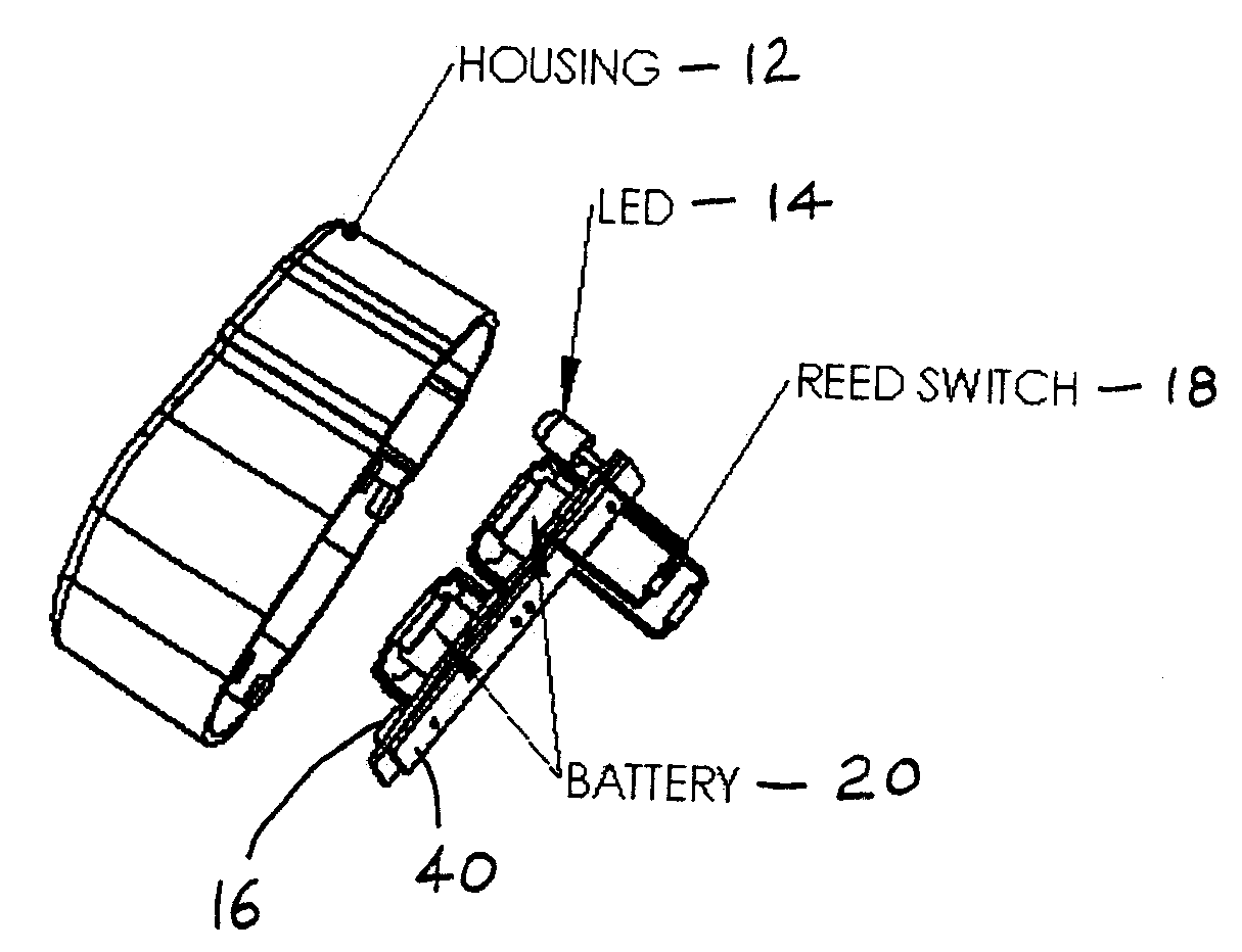
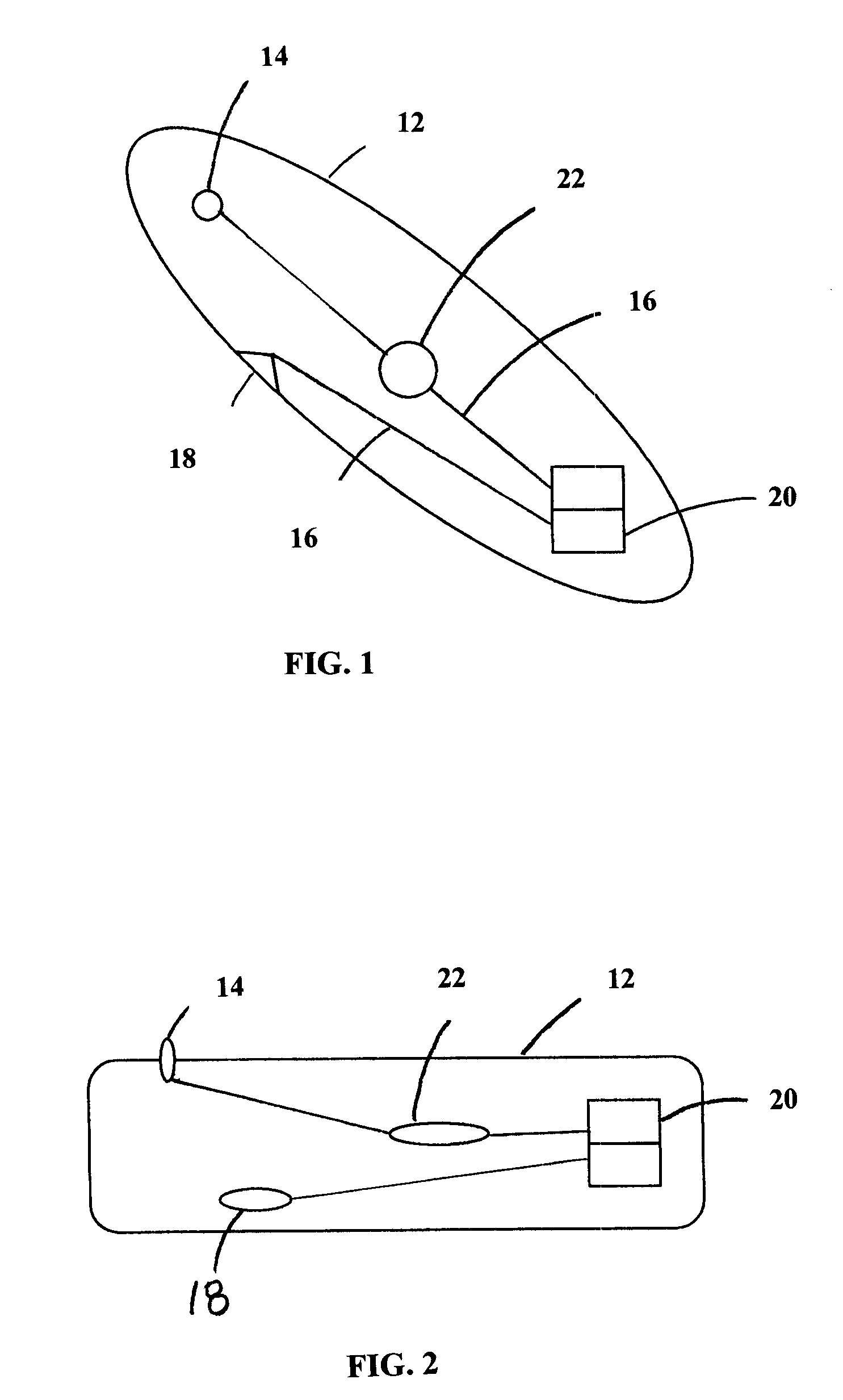
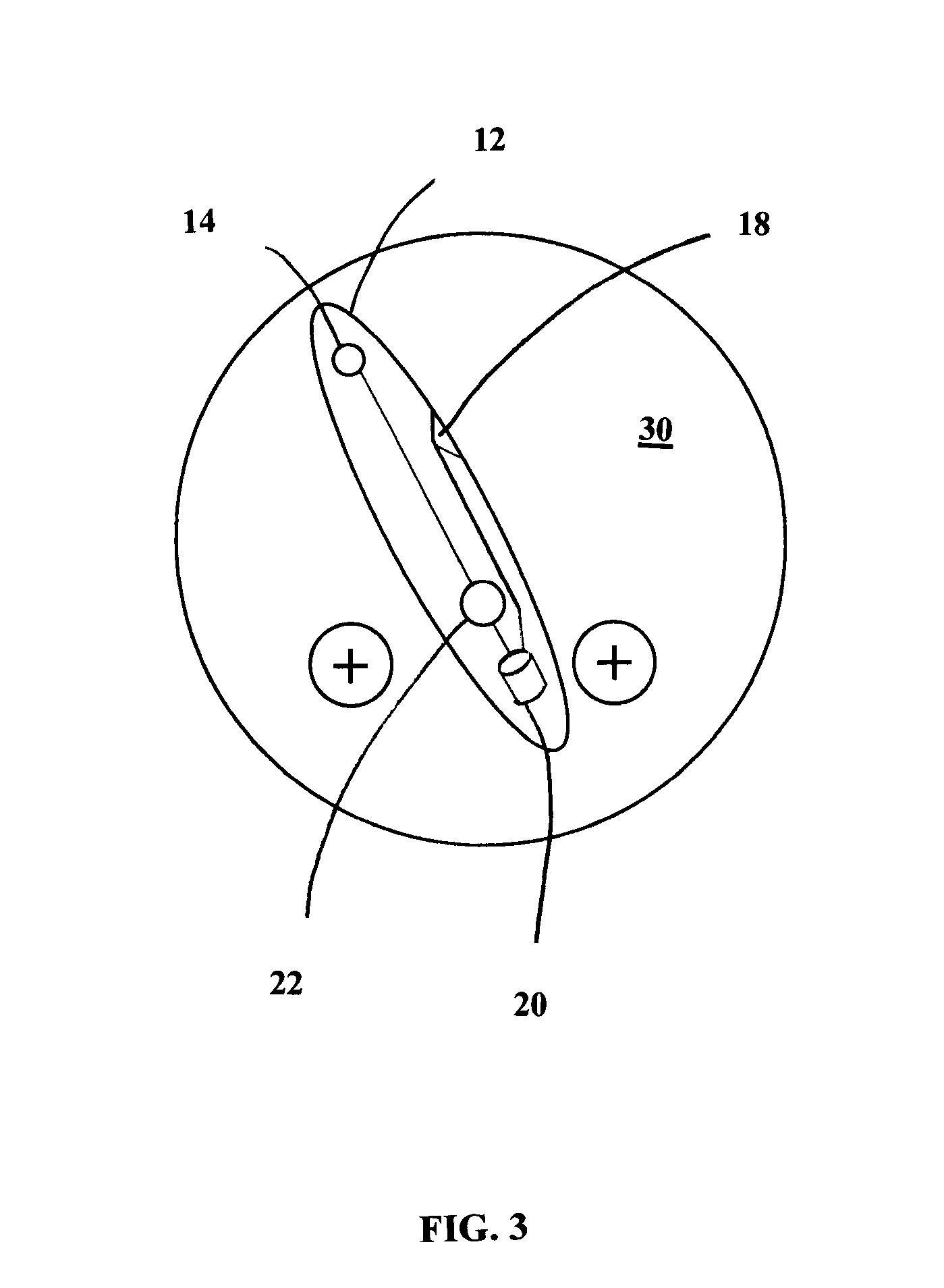
[0020]FIG. 1 is an schematic, top plan view of the present invention. In this view, the plane of the door to which the invention is mounted is in the plane of the paper. In this version of the invention, the housing 12 of the device is a slipcover, which is placed over the latch handle of an existing deadbolt door lock. The slipcover is preferably constructed of metal or metalized plastic and is dimensioned and configured to be slightly larger than the existing latch. Alternatively, the slip cover may be constructed from a flexible or elastic material so that the slipcover will fit snugly over the handle without any loose edges. The slipcover has an outside surface and an inside surface; see FIG. 4. The inside surface of the slipcover is next to the door and has an opening to receive the existing deadbolt latch handle. FIGS. 1 and 2 illustrate that the outside surface has a visible signal...


PUM


Abstract

A self-contained handle assembly for a door provides a light emitting diode which indicates whether the door is locked or unlocked. The LED blinks when the door is locked and thus provides an active reminder of the position of the deadbolt.

Description

CROSS-REFERENCE TO RELATED APPLICATIONS[0001]Priority is hereby claimed to provisional application Ser. No. 61 / 020,451, Filed Jan. 11, 2008, which is incorporated herein by reference.FIELD OF THE INVENTION[0002]This invention relates to a deadbolt latch handle or latch handle cover for use in door lock assemblies. More specifically, this invention relates to an illuminated signal (preferably a light-emitting diode) incorporated in the deadbolt latch handle or handle cover. The signal is activated when the latch handle is secured in a locked position, indicating that the deadbolt is engaged and the door is locked.DESCRIPTION OF THE PRIOR ART[0003]The ever increasing number of residential burglaries in recent years has intensified the need for alarm systems and effective locking mechanisms. Typical residential alarm systems include a plurality of sensor mechanisms at various entrance points, the sensors connected by external wiring to an indicator panel or some other control panel. Ty...

Claims


Application Information

Patent Timeline
Patent Type & Authority Patents(United States)
IPC IPC(8): G08B21/00E05B39/04E05B41/00H01H27/06G08B13/08
CPCE05B41/00E05B17/10Y10T70/8027Y10T70/8081
Inventor SCHENSKY, DAN
Owner SCHENSKY DAN
Why Eureka
Try Eureka