
Multi-band antenna apparatus disposed on a three-dimensional substrate, and associated methodology, for a radio device

a multi-band antenna and antenna technology, applied in the direction of antenna supports/mountings, resonant antennas, radiating element structural forms, etc., can solve the problems of increasing the difficulty of antenna transducer design, incompatible network infrastructures deployed in different areas, and the sharing of antenna transducer elements between different circuit paths

Active Publication Date: 2010-05-11
MALIKIE INNOVATIONS LTD
View PDF23 Cites 15 Cited by
  • Summary
  • Abstract
  • Description
  • Claims
  • Application Information

AI Technical Summary

Benefits of technology

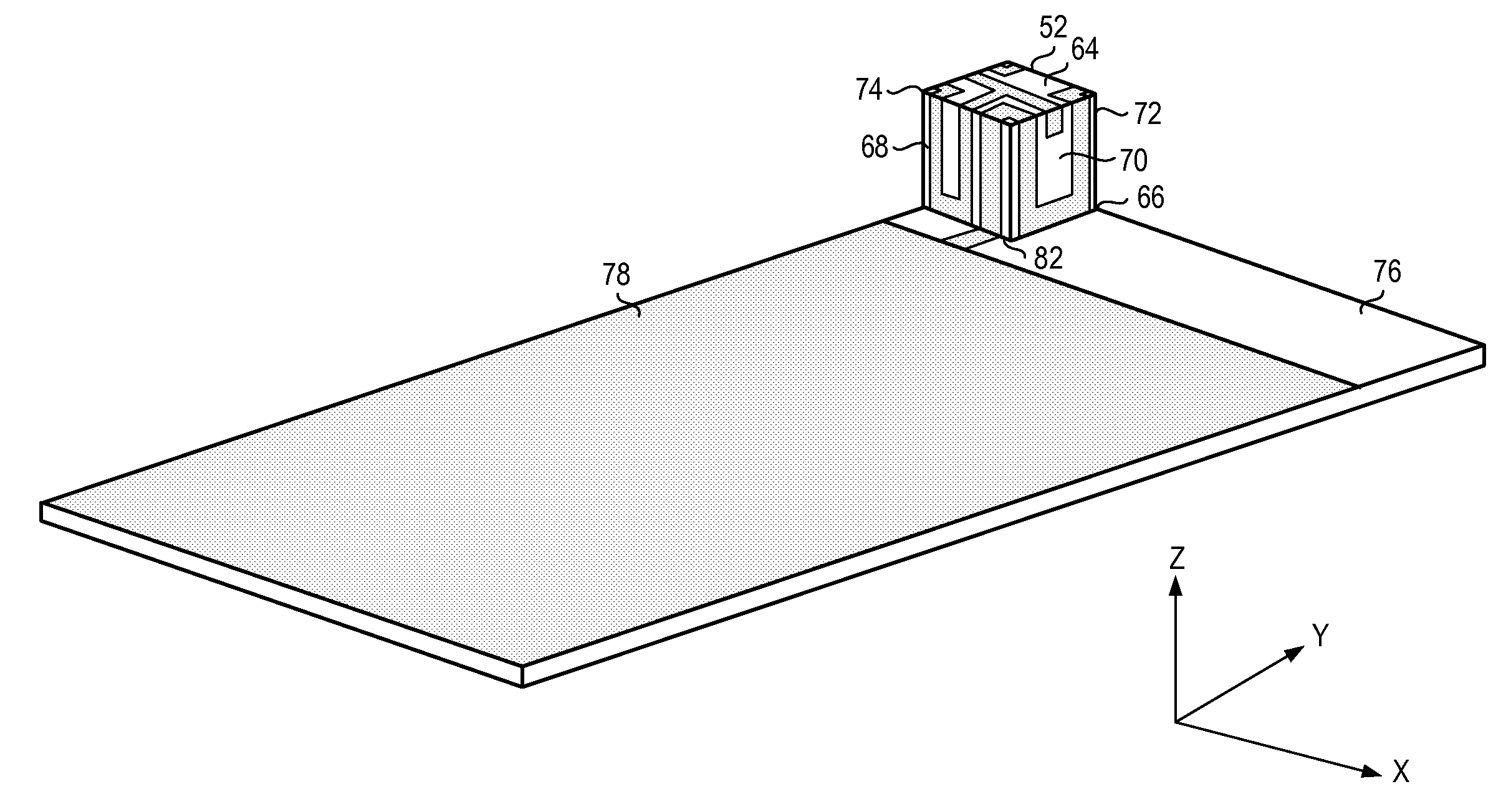
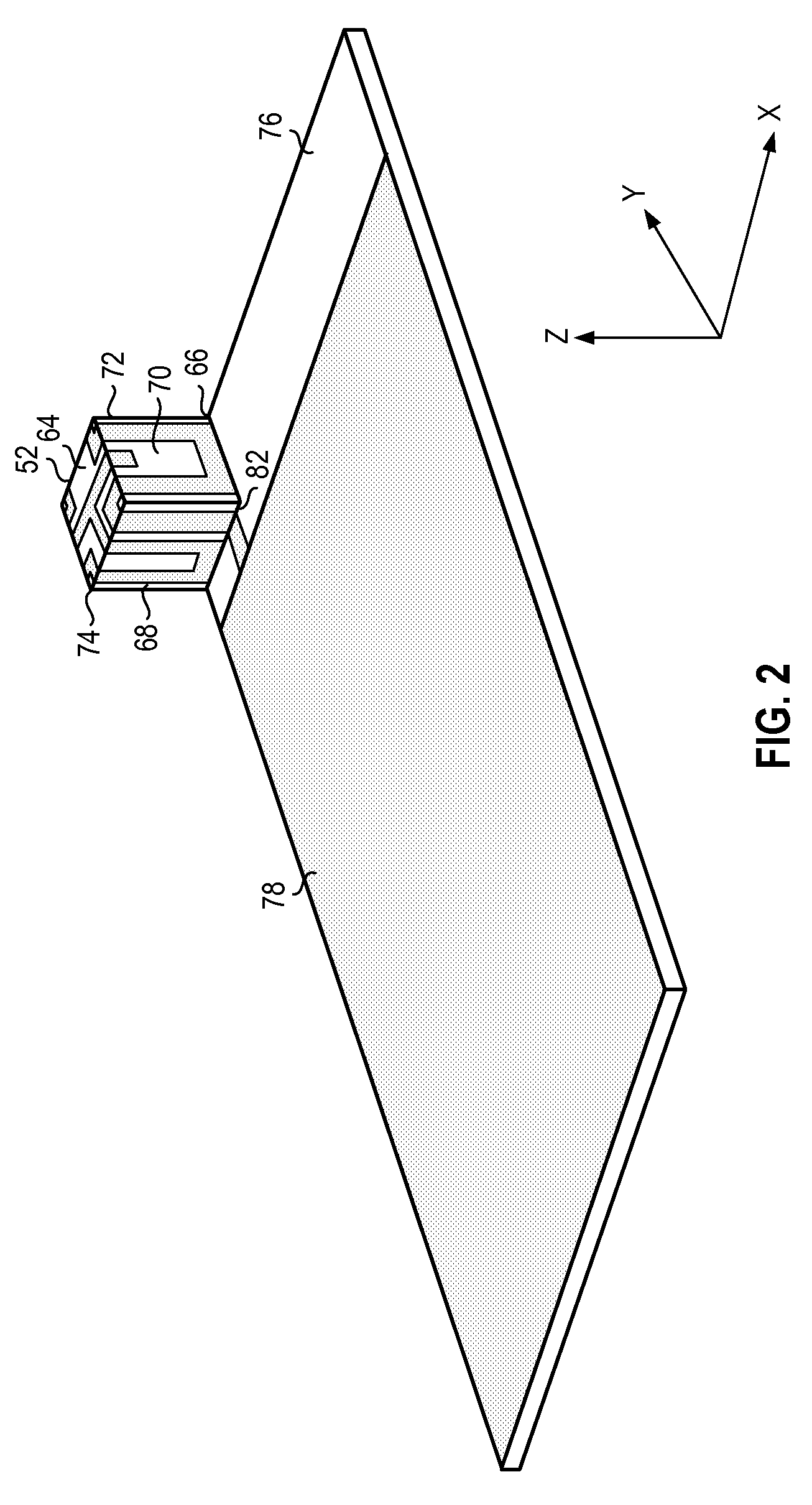
[0002]The antenna includes radiation elements comprising a strip including an impedance matching element disposed upon the external surfaces of a three-dimensional rectilinear substrate, such as a parallelepiped, cube, or pyramidal frustum. The length of the strip is chosen to efficiently transduce RF energy in at least one frequency band of as many as four or more frequency bands. Since a relatively long strip antenna is wound around a very compact substrate, the antenna is of compact dimensions and exhibits stable and relatively wide resonant frequency band characteristics and radiation patterns.

Problems solved by technology

The network infrastructures deployed in the different areas are not necessarily compatible.
Sharing of antenna transducer elements between the different circuit paths, however, presents unique challenges.
And, as mobile station constructions become increasingly miniaturized, housed in housings of increasingly small package sizes, antenna transducer design becomes increasingly difficult, particularly in multi-mode mobile stations when the different modes operate at different frequencies.
Such additions, however, increase the volumetric dimensions of the antenna, as well as its weight.
The additional resonant branches make the antenna difficult to tune and sometimes introduce EMC and EMI, which interferes with transducing of signal energy.

Method used


Image

  • Multi-band antenna apparatus disposed on a three-dimensional substrate, and associated methodology, for a radio device
  • Multi-band antenna apparatus disposed on a three-dimensional substrate, and associated methodology, for a radio device
  • Multi-band antenna apparatus disposed on a three-dimensional substrate, and associated methodology, for a radio device

Examples


Embodiment Construction

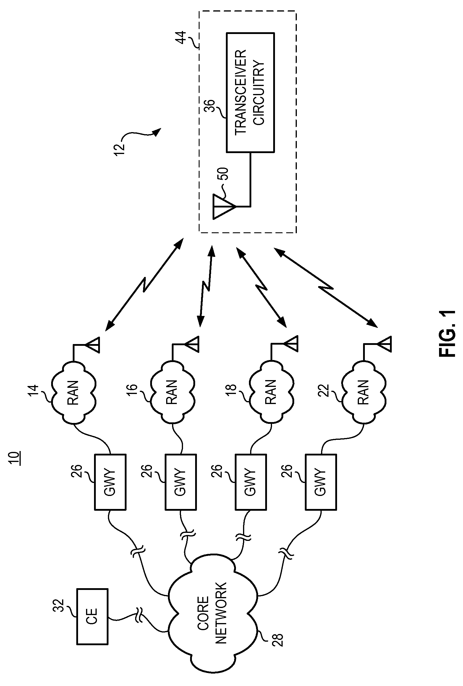
[0018]The present invention, accordingly, advantageously provides compact, lightweight antenna apparatus, and an associated method, for a mobile station, or other radio device, operable over multiple frequency bands.

[0019]Through operation of an embodiment of the present invention, a manner is provided by which to form a hybrid strip antenna of a multi-mode mobile station, or other radio device, operable, e.g., at the 800 / 900 / 1800 / 1900 MHz frequency bands.

[0020]In one aspect of the present invention, an antenna for a multi-mode mobile station is formed of a cube-shaped dielectric antenna substrate, the surfaces of which carry an end-fed antenna strip, formed of a strip of metal or other conductive material having a length, width and thickness. The length of the strip is much longer than the dimensions of any one face of the antenna substrate, requiring the strip to be folded at least part way over different faces of the antenna substrate. In other words, the length of the antenna st...


PUM


Abstract

Antenna apparatus, and an associated methodology, for a multi-frequency-band-capable radio device, such as a quad-band mobile station. The antenna apparatus is formed from a three-dimensional rectilinear non-conductive dielectric antenna substrate, such as cube. An elongated radiation element is disposed over multiple surfaces of the antenna substrate. A T-shaped impedance matching element located at the end of the radiation element permits the antenna input impedance to be matched to a communications device. The length of the radiation element is selected to be substantially equal to a quarter wavelength of the lowest frequency band at which the antenna operates.

Description

[0001]The present invention relates generally to an antenna construction for a mobile station, or other radio device, operable over multiple frequency bands. More particularly, the present invention relates to antenna apparatus, and an associated methodology for forming a hybrid strip antenna of a multi-mode mobile station, or other radio device, operable, e.g., at the 800 / 900 / 1800 / 1900 / 2100 MHz frequency bands.[0002]The antenna includes radiation elements comprising a strip including an impedance matching element disposed upon the external surfaces of a three-dimensional rectilinear substrate, such as a parallelepiped, cube, or pyramidal frustum. The length of the strip is chosen to efficiently transduce RF energy in at least one frequency band of as many as four or more frequency bands. Since a relatively long strip antenna is wound around a very compact substrate, the antenna is of compact dimensions and exhibits stable and relatively wide resonant frequency band characteristics ...

Claims


Application Information

Patent Timeline
Patent Type & Authority Patents(United States)
IPC IPC(8): H01Q1/38
CPCH01Q5/357H01Q1/38
Inventor WEN, GEYIRAO, QINJIANGPECEN, MARK
Owner MALIKIE INNOVATIONS LTD
Learn More