Rendering a simulated vector marker stroke

a vector and stroke technology, applied in the field of computer animated drawings, can solve the problems of inability to provide an end-user, inability to provide such natural media materials or marker strokes in a vector environment, confusion, etc., and achieve the effect of quick and efficient rendering of vector marker strokes

Active Publication Date: 2010-05-11
AUTODESK INC
View PDF37 Cites 11 Cited by
  • Summary
  • Abstract
  • Description
  • Claims
  • Application Information

AI Technical Summary

Benefits of technology

[0020]One or more embodiments of the invention provide the ability to quickly and efficiently render a vector marker stroke in a vector-based drawing program. The stroke rendering is essentially broken into two components:

Problems solved by technology

However, such CAD drawings may be complex, confusing, and fail to provide an end-user (e.g., a potential client of an architect) with a drawing or visualization of the “intent” of the architect or designer.
However, prior art programs fail to provide the ability to present such natural media materials or marker strokes in a vector environment.
Thus, it has always been a challenge for digital artists to achieve natural hand-drawn effects in a vector-based drawing program.
While the prior art has attempted to create vector-based strokes that appear organic, the prior art has failed to provide the ability to simulate or model natural media materials such as for a magic marker.
In a vector environment, achieving the look of marker strokes is challenging, because when strokes overlap, there is a higher saturation of ink in the overlap area (and, consequently a darker color).
A challenge of modeling this is determining the location and nature of the overlap areas with rendering techniques that allow the strokes to be modified in near-real time.
However, such prior art simulations are slow due to the amount of processing that must be performed.
Thus, prior art marker stroke techniques fail to achieve an easy, intuitive, fast, vector-based modifiable means for providing a hand-drawn look of a marker stroke.
However, if you have a shader that works on a surface, such neighbor examination is more difficult or impossible.
However, there is no mechanism for obtaining the value of neighboring pixels in the same / current pass.

Method used


Image

  • Rendering a simulated vector marker stroke
  • Rendering a simulated vector marker stroke
  • Rendering a simulated vector marker stroke

Examples


Embodiment Construction

[0033]In the following description, reference is made to the accompanying drawings which form a part hereof, and which is shown, by way of illustration, several embodiments of the present invention. It is understood that other embodiments may be utilized and structural changes may be made without departing from the scope of the present invention.

Overview

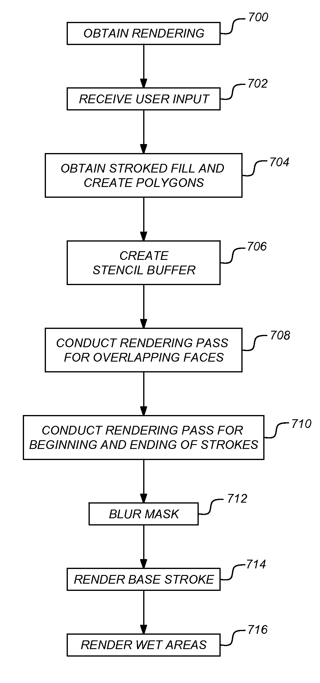
[0034]Embodiments of the invention provide a method, apparatus, system, technique, etc. for modeling / simulating a marker / magic marker natural media material in a vector-based drawing program.

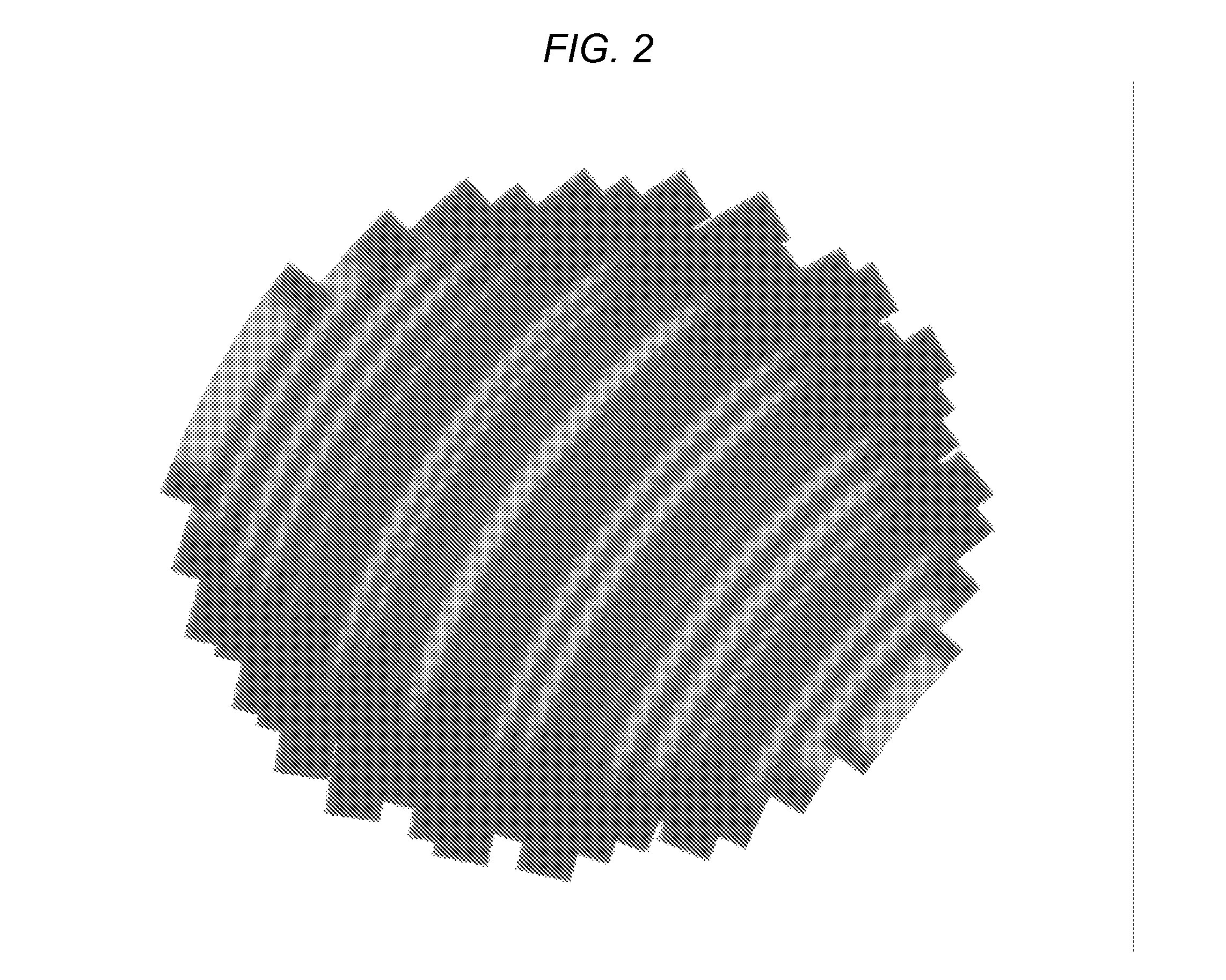
[0035]As indicated above, in a vector environment, achieving the look of marker strokes is challenging, because when strokes overlap, there is a higher saturation of ink in the overlap area (and, consequently a darker color). Additionally, ink bleeds from the overlap area into adjacent stroke areas. A challenge of modeling this is determining the location and nature of the overlap areas with rendering techniques that allow the strokes to be modif...


PUM


Abstract

An apparatus, method, and article of manufacture are configured to display a vector marker stroke. A stroked fill of vector splines and polygons having faces along the spline are created based on a user input marker stroke. A stencil buffer is created indicating the number of vector faces incident at each pixel. When the number indicates that a pixel has overlapping faces, a pixel shader (that determines an opacity value for the pixel in a mask) is executed as many times as the number. When the number indicates that a pixel has at least one face and is at a beginning or an ending of the stroke, the shader is executed to add to the opacity value. A blur shading operation is executed on each of the pixels. The stroked fill is rendered and a wet color is rendered, using the mask, on top of the stroked fill.

Description

CROSS-REFERENCE TO RELATED APPLICATIONS[0001]This application is related to the following co-pending and commonly-assigned patent applications, which applications are incorporated by reference herein:[0002]U.S. patent application Ser. No. 11 / 268,797, entitled “AUTOMATIC ELEMENT SUBSTITUTION IN VECTOR-BASED ILLUSTRATIONS”, by Mason J. Foster, filed on Nov. 8, 2005;[0003]U.S. patent application Ser. No. 11 / 268,796, entitled “DRAWING STYLE DOMAINS”, by Mason J. Foster, Jose Madeira de Freitas Garcia, and Joseph Cleveland Ard, filed on Nov. 8, 2005;[0004]U.S. patent application Ser. No. 11 / 286,658, entitled “CASTING SHADOWS”, by Mason J. Foster, filed on Nov. 23, 2005; and[0005]U.S. patent application Ser. No. 11 / 286,535, entitled “STROKED FILL”, by Nikolai Sander and Mason J. Foster, filed on Nov. 23, 2005.BACKGROUND OF THE INVENTION[0006]1. Field of the Invention[0007]The present invention relates generally to computer animated drawings (CAD) such as architectural renderings mechanica...

Claims


Application Information

Patent Timeline
Patent Type & Authority Patents(United States)
IPC IPC(8): G06T11/20
CPCG06T15/40G06T11/40
Inventor SANDER, NIKOLAI
Owner AUTODESK INC
Why Eureka
Try Eureka