Method for controlling percussion device, software production, and percussion device

a percussion device and software production technology, applied in the direction of portable drilling machines, static/dynamic balance measurement, instruments, etc., can solve the problems of natural reduction of drilling efficiency, inability to efficiently utilize energy in reflected waves, and problems with the durability of drilling equipmen

Inactive Publication Date: 2010-05-18
SANDVIK MINING & CONSTR OY
View PDF25 Cites 17 Cited by
  • Summary
  • Abstract
  • Description
  • Claims
  • Application Information

AI Technical Summary

Benefits of technology

[0013]The invention provides the advantage that the energy in the reflected wave can now be better utilized in drilling. When the reflected wave has reached the percussion device end of the tool, the tensile stress component in the reflected wave is reflected back toward the drill bit as a compression stress wave. A new primary compression stress wave generated with the percussion device is summed to this reflected compression stress wave, whereby the sum wave formed by the reflected and primary compression stress waves has a higher energy content than the compression stress wave generated with the percussion device only. In addition, the solution of the invention ensures that there is always a good contact between the drill bit and rock. This is due to the fact that there are only compression stress waves propagating toward the drill bit of the tool. When, at the first end of the tool, a new compression stress wave generated by the percussion device is summed to the reflected stress wave, the sum wave is always a compressive stress wave. Therefore, no tensile stress waves propagate toward the drill bit of the tool, which may weaken the contact between the drill bit and rock. Further, when applying the solution of the invention, the feed force may be lower than before, because a good contact between the drill bit and rock is maintained without having to compensate for the effect of tensile stress waves with a high feed force.
[0014]An essential idea of an embodiment of the invention is that the shape of the sum wave propagating in the tool from the percussion device toward the drill bit is made as desired by fine-adjusting the impact frequency. The fine-adjustment affects the summing of the compression stress wave reflected from the first end of the tool and the primary compression stress wave generated with the percussion device and, thus, also the shape of the sum wave. By setting the impact frequency higher than the setting defined on the basis of the length of the drilling equipment, a progressive sum wave is obtained. By making the impact frequency lower, it is, in turn, possible to lengthen the sum wave, which in practice lengthens the effective time of compression stress. It is naturally also possible to lengthen the sum wave by increasing the impact frequency sufficiently, whereby the reflected wave attaches to the rear of the generated primary compression stress wave.
[0015]An essential idea of an embodiment of the invention is that in extension rod drilling, the impact frequency of the percussion device is set to correspond to the propagation time of a stress wave in one extension rod. The reflected waves propagating from one end of the tool toward the percussion device then propagate to the connection joints between the extension rods substantially simultaneously with the primary compression stress waves propagating from the opposite direction. When arriving substantially simultaneously to the connection joint, the compression stress wave and the reflected wave are summed, whereby the tensile stress component in the reflected wave is neutralized and no tensile stress is, thus, directed to the connection. This way, it is possible to improve the durability of the connections between extension rods.

Problems solved by technology

Today, the energy in the reflected waves cannot be efficiently utilized in drilling, which naturally reduces the efficiency of drilling.
On the other hand, it is known that reflected waves cause problems to the durability of drilling equipment, for instance.

Method used


Image

  • Method for controlling percussion device, software production, and percussion device
  • Method for controlling percussion device, software production, and percussion device
  • Method for controlling percussion device, software production, and percussion device

Examples


Embodiment Construction

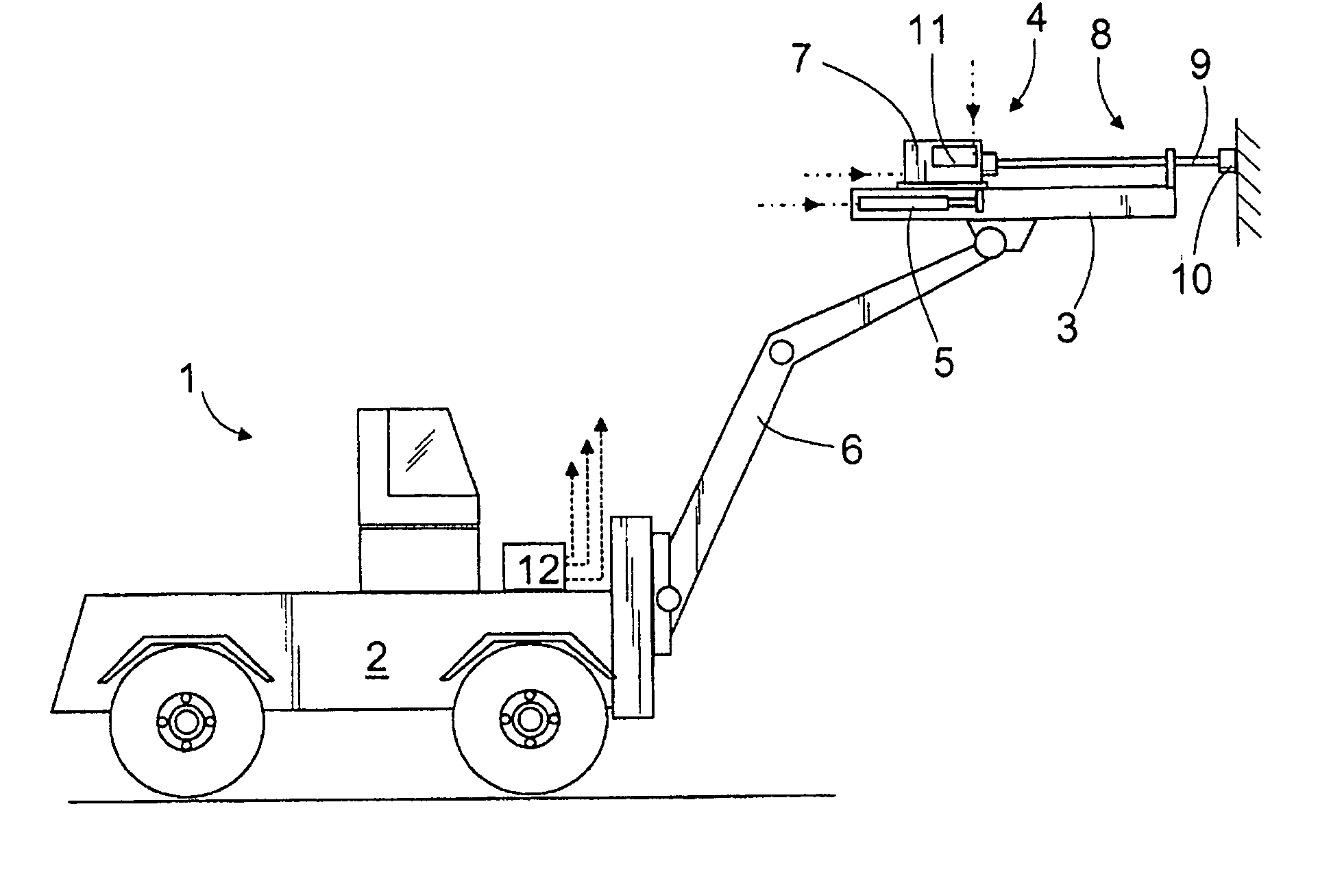
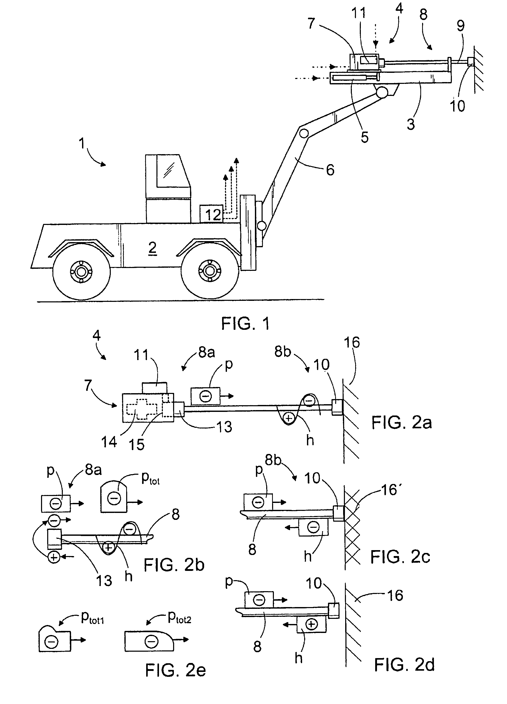
[0033]The rock drilling rig 1 shown in FIG. 1 comprises a carrier 2 and at least one feeding beam 3, on which a movable rock-drilling machine 4 is arranged. With a feeding device 5, the rock-drilling machine 4 can be pushed toward the rock to be drilled and, correspondingly, pulled away from it. The feeding device 5 may have one or more hydraulic cylinders, for instance, that may be arranged to move the rock-drilling machine 4 by means of suitable power transmission elements. The feeding beam 3 is typically arranged to a boom 6 that can be moved with respect to the carrier 2. The rock-drilling machine 4 comprises a percussion device 7 for providing impact pulses to a tool 8 connected to the rock-drilling machine 4. The tool 8 may comprise one or more drill rods and a drill bit 10. The rock-drilling machine 4 may further comprise a rotating device 11 for rotating the tool 8 around its longitudinal axis. During drilling, impact pulses are provided with the percussion device 7 to the t...


PUM

PropertyMeasurementUnit
impact frequencyaaaaaaaaaa
velocityaaaaaaaaaa
impact frequencyaaaaaaaaaa

Abstract

A method and software product for controlling a percussion device belonging to a rock-drilling machine, and a percussion device. The impact frequency of the percussion device is set so that the percussion device forms a new compression stress wave to the tool always when reflected waves from the previous compression stress waves reach a first end of the tool. This requires that the impact frequency be set proportional to the propagation time of the stress wave, whereby the length of the used tool and the propagation velocity of the stress wave in the tool material are to be noted.

Description

CROSS REFERENCE TO RELATED APPLICATIONS[0001]This application is a National Stage of International Application No. PCT / FI2005 / 050257 filed Jun. 30, 2005, and which claims benefit of Finnish Patent Application No. 20040929 filed Jul. 2, 2004, which is incorporated by reference herein in its entirety.BACKGROUND OF THE INVENTION[0002]The invention relates to a method for controlling a percussion device, the method comprising: providing impact pulses with the percussion device during drilling to a tool connectable to a rock-drilling machine; and generating a compression stress wave to the tool to propagate at a propagation velocity dependent on the tool material from a first end to a second end of the tool, with at least some of the compression stress reflecting back from the second end of the tool as a reflected wave that propagates toward the first end of the tool; and controlling the percussion device in the rock-drilling machine and its impact frequency.[0003]The invention further r...

Claims


Application Information

Patent Timeline
Patent Type & Authority Patents(United States)
IPC IPC(8): B25D9/26E21B1/00E21BE21B6/00E21B44/08
CPCB25D9/26E21B44/08E21B6/00E21B1/00B25D2250/221
Inventor KESKINIVA, MARKKUMAKI, JORMAHELIN, AIMOESKO, MAURIAHOLA, ERKKI
Owner SANDVIK MINING & CONSTR OY
Why Eureka
Try Eureka