Compact wheelchair restraint system with housing and release

a wheelchair and housing technology, applied in the direction of load securing, transportation and packaging, transportation items, etc., can solve the problems of unreliable after repeated use, complex installation and maintenance, and difficult use of systems,

Active Publication Date: 2010-05-18
SURE LOK INT
View PDF23 Cites 43 Cited by
  • Summary
  • Abstract
  • Description
  • Claims
  • Application Information

AI Technical Summary

Benefits of technology

[0012]In accordance with the present invention, an apparatus is provided for securing a wheelchair from movement within a wheelchair space or station in a mass transit vehicle. One or more retractor spools are located in a common housing, with the spools, their associated flexible webbed belts, and their actuator mechanisms contained within the same housing. The housing is designed so that only hooks and a small portion of the end of the flexible belts protrude from the housing. The housing presents an essentially flush or flat surface on its exposed exterior, thereby permitting the housing to be secured within or to a vehicle bulkhead, or under a foldable vehicle seat while presenting little or no obstacle to other passengers using the vehicle when the retractor system is not in use.
[0013]The plurality of retractor spools contained within the housing are physically aligned to permit a common mechanical or electromechanical release mechanism to directly engage the retractor mechanism to provide a simple, inexpensive and reliable means for locking and unlocking the retractor mechanism, thereby allowing the wheelchair-engaging belts to be easily positioned and locked to secure the wheelchair from movement within a typical mass transit vehicle.
[0015]The apparatus herein described, by virtue of its compact configuration, is also easily mountable underneath a foldable seat assembly, allowing the apparatus to be placed out of the way when not in use and allowing the wheelchair station to be utilized for ambulatory passengers, as needed. Further, the controls for the apparatus are central, allowing the device to be easily operated by the vehicle operator or by the occupant of a wheelchair without assistance from the vehicle operator or other passengers. The system may be provided with a positive locking actuator which provides visual indicia of the locked position of the retractors within the assembly. Moreover, the actuator may be provided with an electrically operated actuator. In either case, the apparatus may also be provided with a time-delay circuit or mechanism, which will allow easy manipulation of the belts within the retractor assembly for a limited period of time, following which the retractors will revert to the locked position without further action on the part of the operator of the vehicle or occupant of the wheelchair. Additionally, the system may be equipped with a remote annunciator which alerts the user as well as the driver of the vehicle when the retractors within the assembly are in the unlocked (and hence, unsafe) position.

Problems solved by technology

However, a recognized problem in accommodating such mobility aids in buses, train cars, and the like, is the need for reliably securing the mobility aid to prevent its unwanted movement while the vehicle is in motion.
While this type of system provides some measure of safety to the wheelchair occupant, these systems are difficult to use for a number of reasons.
However, each belt assembly is separate and separately operable, requiring the assistance of an operator.
However, this invention suffers from one of the limitations of the previously described prior art, in that it uses separate exposed retractor bodies which can easily snag or catch other passengers in the vehicle.
Further, Magnuson, et al. relies upon a complicated system of cables for interconnecting the remote actuator to the retractors, which is expensive, complicated to install and maintain, and unreliable after repeated use.
All of the prior art systems, however, are limited in that they require the simultaneous activation of a control, usually to release a belt retractor, coupled with movement of the belt to a securing position on a wheelchair.

Method used


Image

  • Compact wheelchair restraint system with housing and release
  • Compact wheelchair restraint system with housing and release
  • Compact wheelchair restraint system with housing and release

Examples


Embodiment Construction

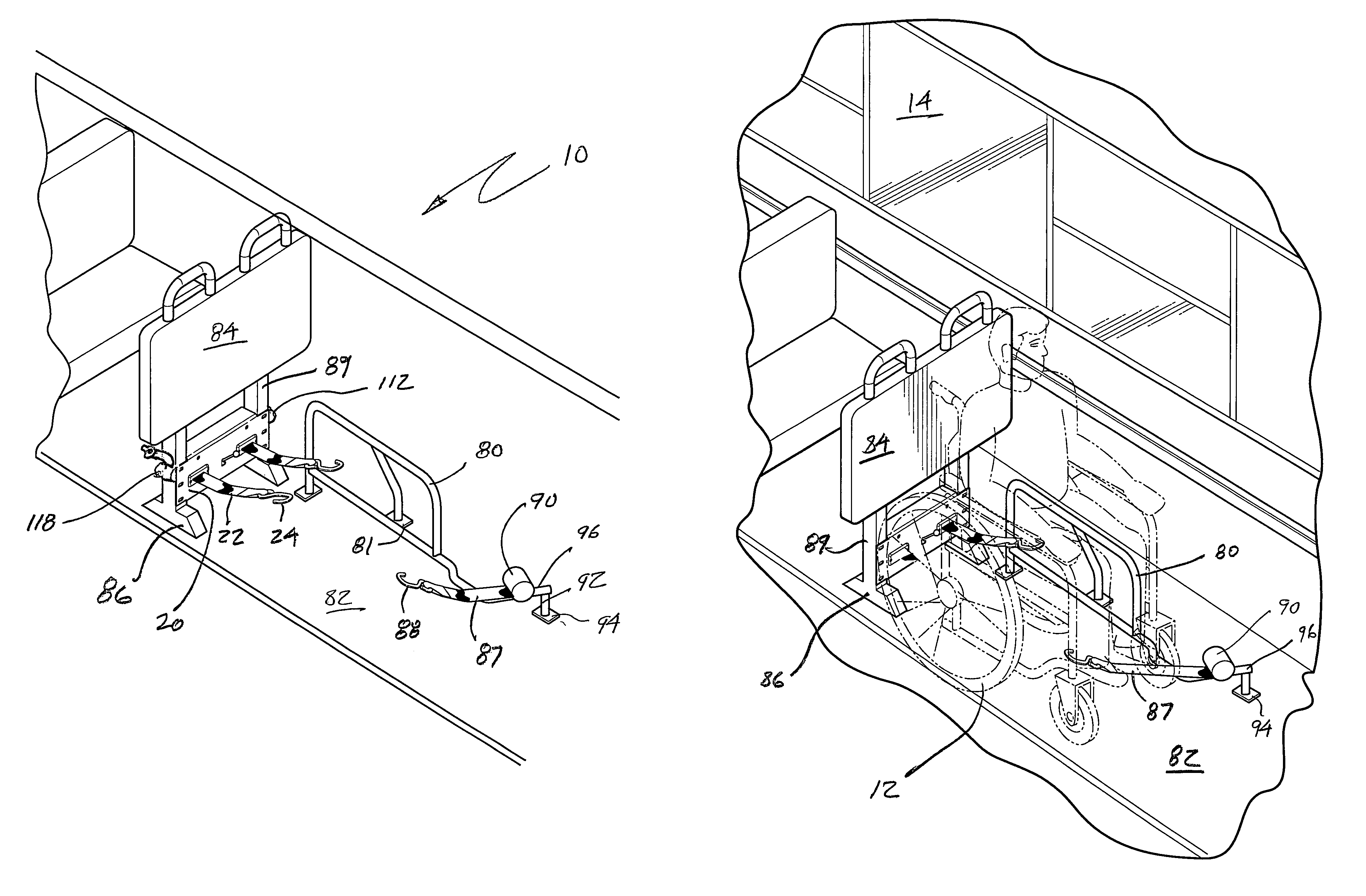
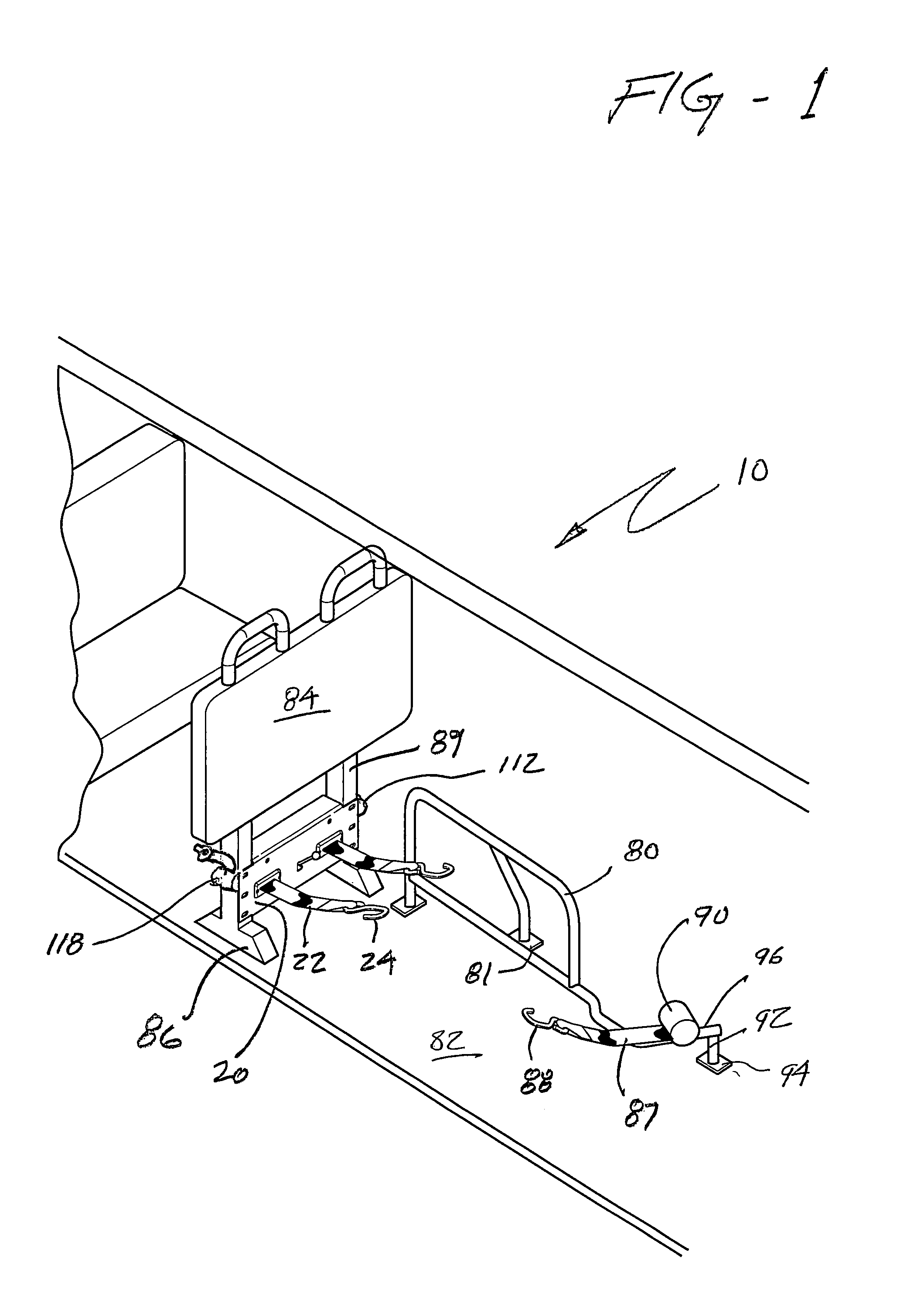
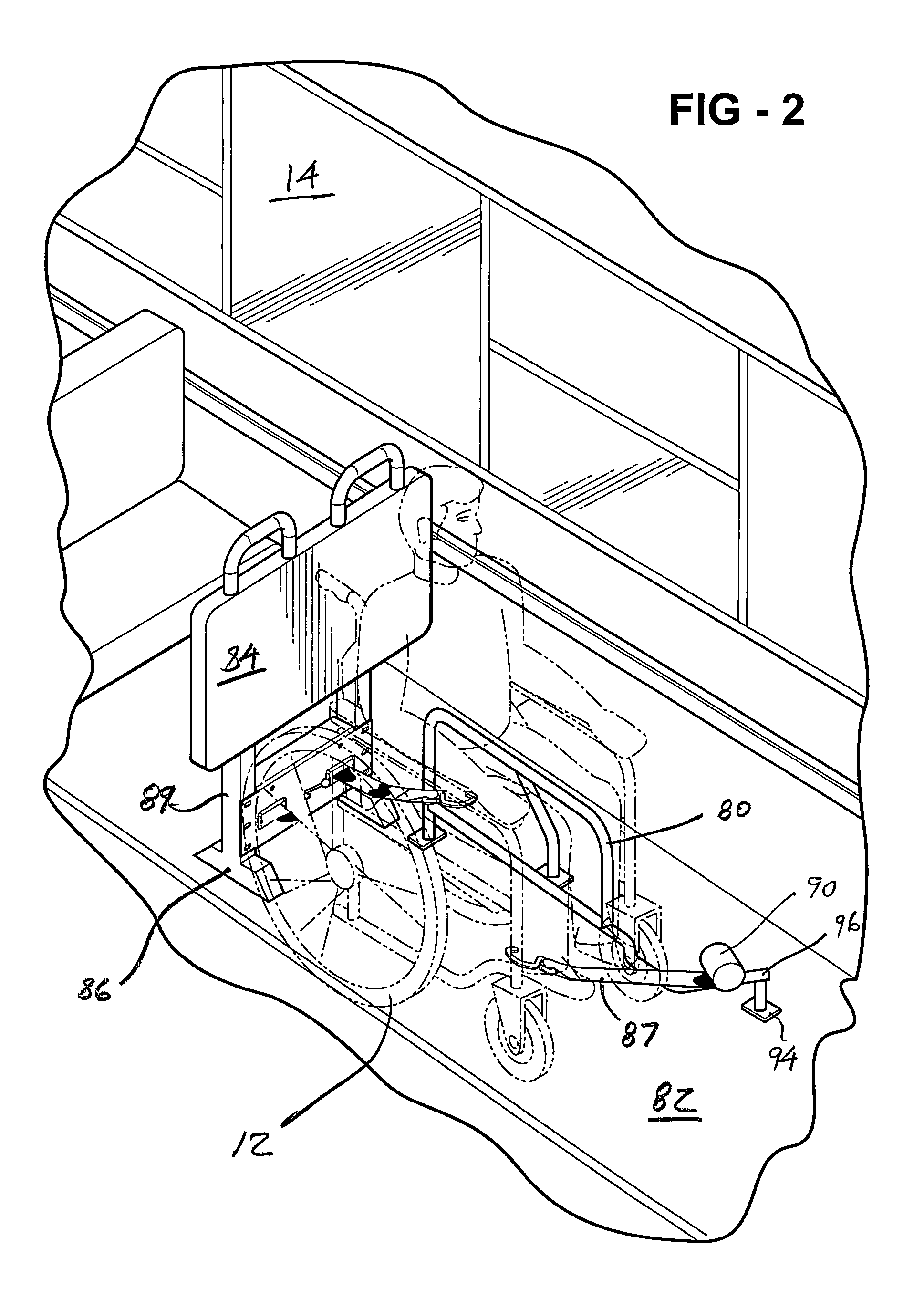
[0030]With reference first to FIG. 1 and FIG. 2, the overall environment in which the invention is utilized will be best appreciated. In a typical vehicle 14, the apparatus 10 is utilized to secure a wheelchair 12 within a pre-designated location or “station” within a vehicle, such as a bus, train car or other vehicle. One lateral side of the area or station in which the wheelchair 12 is secured is provided with a barrier 80 which is affixed to the floor 82 of the vehicle 14 utilizing mounting plates 81. Barrier 80 serves to restrict the lateral movement of a wheelchair 12 positioned within the wheelchair station, and also to provide a supplemental hand hold which may be used by a wheelchair occupant during the process of securing the wheelchair 12 in the station.

[0031]Typically, the wheelchair station is defined in the rear by bulkhead 84, at one lateral side by the barrier 80, at the other lateral side by the aisle of the vehicle, and in the front by the back of the next seat or c...


PUM


Abstract

An apparatus for restraining a mobility aid in the interior of a vehicle includes two or more retractor spools contained within a common housing. The retractor spools carry flexible webbed belts, and are operated by common actuator mechanism having a direct mechanical attachment to the spools. The various elements of the apparatus are contained within a common housing which is easily mounted to a bulkhead or under a foldable seat. A third retractor is mounted in opposition permitting both the front and rear of the mobility aid to be easily secured by the occupant of the mobility aid without assistance of the operator of the vehicle. The operative portions of the retractor are designed to be positioned so as not to present an obstacle to other users of the vehicle in which the apparatus may be installed. A timing mechanism is provided for at least one of the retractor spools to allow at least one of the retractor spools to be freely manipulated during a predetermined time interval.

Description

PRIORITY CLAIM[0001]This application claims the benefit of U.S. Provisional Application No. 60 / 847,260, filed Sep. 26, 2006.FIELD OF THE INVENTION[0002]The invention relates to an apparatus for securing an object, such as a wheelchair, to the interior of a vehicle. More particularly, the invention includes a compact and self-contained assembly comprising a plurality of belt retractors operated by a single control.BACKGROUND[0003]Accommodation of mobility aids, such as wheelchairs, in public transit vehicles is now commonplace. For the convenience of all of the passengers, methods and equipment have been developed for quickly and easily securing wheelchairs in mass transit vehicles. However, a recognized problem in accommodating such mobility aids in buses, train cars, and the like, is the need for reliably securing the mobility aid to prevent its unwanted movement while the vehicle is in motion.[0004]It is desirable in mass transit vehicles to have mobility aid securement systems wh...

Claims


Application Information

Patent Timeline
Patent Type & Authority Patents(United States)
IPC IPC(8): B60P7/08
CPCA61G3/0808
Inventor CARDONA, EDGARDO
Owner SURE LOK INT
Why Eureka
Try Eureka