Conformable prosthesis for implanting two-piece heart valves and methods for using them

a technology of two-piece heart valves and prostheses, which is applied in the field of two-piece heart valve prosthesis and the method of using them, can solve the problems of reducing the accuracy of the implanted prosthesis, and increasing the chance of mistakes, so as to enhance the interference fit, enhance the sealing effect, and enhance the effect of sealing

Active Publication Date: 2010-05-18
MEDTRONIC INC
View PDF119 Cites 186 Cited by
  • Summary
  • Abstract
  • Description
  • Claims
  • Application Information

AI Technical Summary

Benefits of technology

[0008]In one embodiment, the sewing cuff may be conformable for at least partially adopting a shape of tissue above or within the biological annulus. In addition or alternatively, the sewing cuff may be penetrable by fasteners for securing the sewing cuff to tissue surrounding the sinus cavity. Optionally, the sewing cuff may include one or more conformable elements, e.g., a plurality of flexible ribs and / or a lattice, e.g., to enhance sealing between the prosthetic valve and the annulus member. For example, the conformable element(s) may include a silicone, foam, fabric, or other core secured within fabric to provide the sewing cuff having sufficiently flexibility to conform to yet provide a seal against the surrounding tissue.
[0011]In one embodiment, the sewing cuff may be resiliently flexible for conforming at least partially to the multiple lobular shape of the prosthetic valve and / or to the surrounding tissue, e.g., to enhance a seal between the prosthetic valve, the annular member, and / or the surrounding tissue. In addition or alternatively, the prosthetic valve, annular member, and / or sewing cuff may include a flexible skirt for enhancing a seal between the prosthetic valve and the annular prosthesis. Such enhanced seals may facilitate implanting a prosthetic valve having a multiple-lobular shape, e.g., corresponding to the supra-annular above a biological annulus, and an annular member having a substantially circular shape, e.g., corresponding to the biological annulus.
[0013]In accordance with yet another embodiment, a method is provided for implanting a prosthetic heart valve assembly to replace a natural or prosthetic heart valve implanted within a biological annulus below a sinus cavity. An annular member may be introduced into the biological annulus to direct tissue surrounding the biological annulus outwardly, e.g., to at least partially dilate the biological annulus. A valve prosthesis may be advanced into the sinus cavity, and secured relative to the annular member. A flexible sewing cuff or skirt may extend around the annular member that may be engaged by the valve prosthesis for enhancing a seal between the valve prosthesis and the annulus member.
[0015]In addition or alternatively, the rim may include a ramped and / or tapered surface, e.g., upper edge for guiding the lower edge of the valve member into engagement with the rim. In addition, the lower edge of the valve member may include a ramped and / or tapered surface, and / or may include a plurality of tabs or other elements for engaging the rim of the base member. Optionally, the rim may be deflectable radially outwardly (or inwardly) when the lower edge of the valve member is guided into engagement with the rim, the rim being biased to return radially inwardly (or outwardly) to enhance an interference fit between the rim and the valve member.
[0016]In another option, a flexible skirt may extend from the base member and / or valve member for enhancing a seal between the valve member and the base member when the valve member is secured to the base member. For example, the base member may be sufficiently flexible to conform at least partially to the annulus of the heart, and the flexible skirt may deform to accommodate irregularities between the valve member and the base member, e.g., to enhance sealing between the valve member and the base member. The flexible skirt may extend laterally from the valve member and / or base member. For example, the flexible skirt may extend outwardly and / or upwardly from the base member or outwardly and / or downwardly, from the valve member, e.g., such that the flexible skirt enhances contact between the valve member and the base member. Exemplary materials for the flexible skirt may include foam, fabric, and / or silicone.

Problems solved by technology

The sewing rings of either type of prosthetic valve can be tedious and time consuming to secure within a target site, i.e., within an annulus of a heart where a natural heart valve has been removed.
Consequently, this procedure can be very complicated, requiring management and manipulation of many sutures.
The complexity of the procedure also provides a greater opportunity for mistakes and requires a patient to be on cardiopulmonary bypass for a lengthy period of time.
Because the annulus of the heart may not match the circular cross-section of the sewing ring and / or prosthetic valve, the prosthetic valve may not fit optimally within the annulus.
As a result, natural blood hemodynamics through and around the valve may be impaired, resulting in clotting, possible emboli production, and eventual calcification of the valve structure.
When a mechanical or prosthetic valve is then attached to the sewing ring, however, the valve and sewing ring may not mate together effectively, e.g., if the shape of the sewing ring has been distorted to conform to the annulus, which may also impair natural blood hemodynamics, create leaks, and / or otherwise impair performance of the prosthetic valve.

Method used


Image

  • Conformable prosthesis for implanting two-piece heart valves and methods for using them
  • Conformable prosthesis for implanting two-piece heart valves and methods for using them
  • Conformable prosthesis for implanting two-piece heart valves and methods for using them

Examples


Embodiment Construction

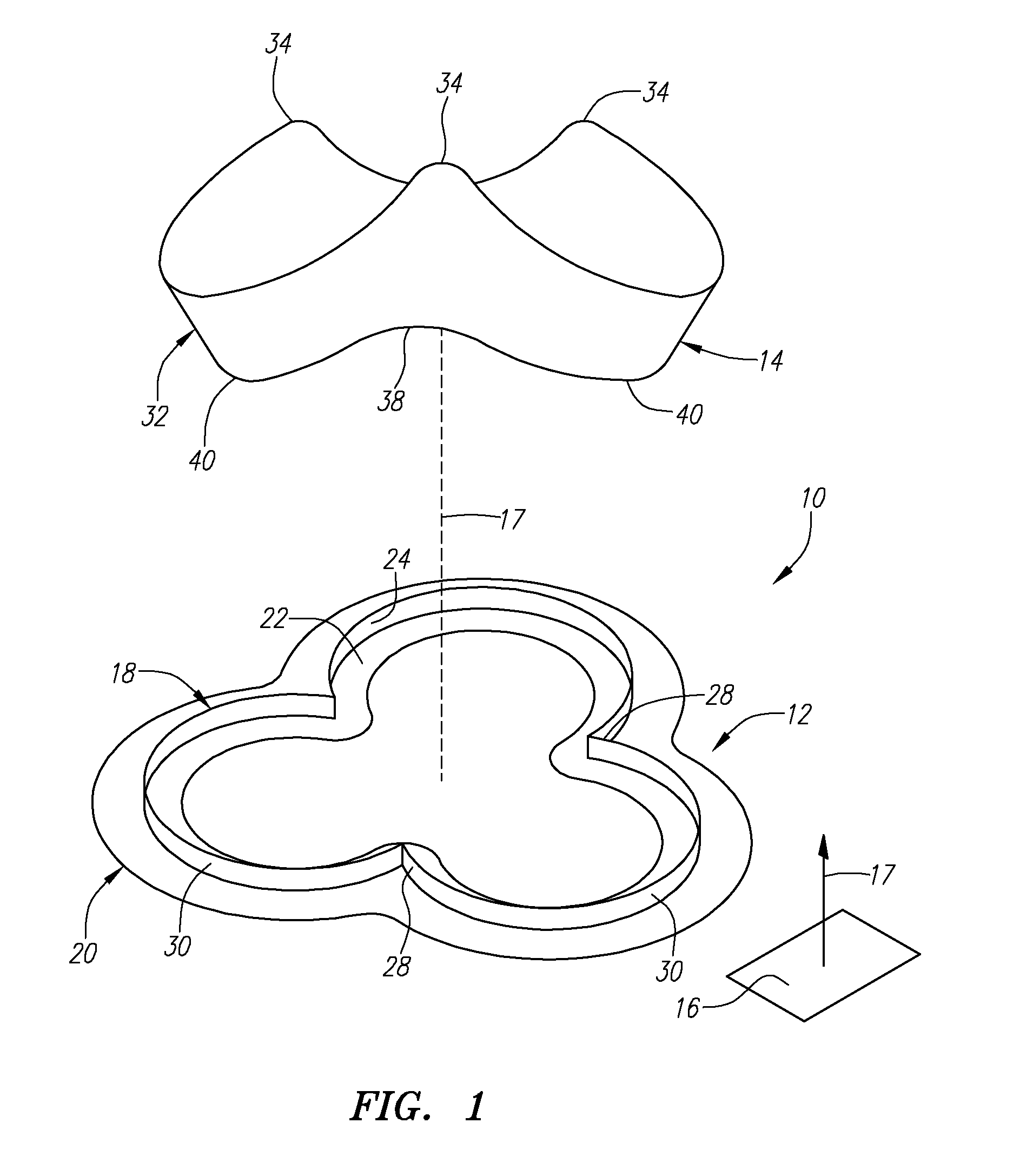
[0075]Turning to the drawings, FIG. 1 shows an exemplary embodiment of a heart valve assembly 10 that generally includes a base member or “gasket member”12 and a valve member or “crown”14. The gasket member 12 is an annular shaped body generally defining a plane 16 and a longitudinal axis 17 extending substantially perpendicular to the plane 16. The gasket member 12 may have a noncircular shape within the plane 16, such as a multiple lobular shape. In one embodiment, the gasket member 12 has a tri-lobular shape, i.e., including three lobes 30 separated by cusps or scallops 28. The shape may correspond generally to a cross-section of a biological annulus within which the gasket member 12 may be implanted, as explained further below. It will be appreciated that the gasket member 12 may define other noncircular shapes within the plane 16, e.g., that may correspond to the anatomy of a patient within which the heart valve assembly 10 is to be implanted.

[0076]The gasket member 12 may incl...


PUM


Abstract

A heart valve assembly includes an annular prosthesis and a valve prosthesis. The annular prosthesis includes an annular ring for dilating tissue within a biological annulus and a conformable sewing cuff extending radially from the annular member. The valve prosthesis includes a frame and a valve component. The annular ring is introduced into the biological annulus to dilate tissue surrounding the biological annulus and the sewing cuff conforms to tissue above the biological annulus. Fasteners are directed through the sewing cuff to secure the annular prosthesis to the biological annulus. The annular prosthesis may include a baleen element for biasing fabric on the annular ring outwardly to enhance sealing against the biological annulus. A valve prosthesis is then advanced into the sinus cavity, and secured relative to the annular prosthesis. The sewing cuff may enhance a seal between the valve prosthesis and annular prosthesis.

Description

BACKGROUND[0001]Prosthetic heart valves can replace defective human valves in patients. For example, one piece valves have been suggested that include sewing rings or suture cuffs that are attached to and extend around the outer circumference of a prosthetic valve. In addition, multiple component valves have also been suggested that include a sewing ring that is separate from a valve component. The sewing rings of either type of prosthetic valve can be tedious and time consuming to secure within a target site, i.e., within an annulus of a heart where a natural heart valve has been removed.[0002]For example, to implant a sewing ring within an annulus of a heart, between twelve and twenty sutures may be secured initially to tissue surrounding the annulus. The sewing ring and / or the entire prosthetic valve may then be advanced or “parachuted” down the sutures into the annulus. Knots may then be tied with the sutures to secure the sewing ring within the annulus, whereupon the sutures ma...

Claims


Application Information

Patent Timeline
Patent Type & Authority Patents(United States)
IPC IPC(8): A61F2/24
CPCA61F2/2409A61F2/2418A61F2/2427A61F2250/0097A61F2220/0016A61F2250/006A61F2210/009A61F2/2412
Inventor LANE, ERNESTDREWS, MICHAEL J.GURSKIS, DONNELL W.
Owner MEDTRONIC INC
Why Eureka
Try Eureka