
Non-destructive testing apparatus for the detection of corrosion

Active Publication Date: 2010-05-18
MATCO SERVICES
View PDF2 Cites 16 Cited by
  • Summary
  • Abstract
  • Description
  • Claims
  • Application Information

AI Technical Summary

Benefits of technology

[0021]Accordingly, a principal object of the present invention is to provide a non-destructive testing device that measures the graphitization or other localized corrosion phenomena in gray iron, ductile cast iron, ferrous alloys, and other magnetic materials.
[0024]A further object of the present invention is to provide a non-destructive testing device for preventing water main failures.

Problems solved by technology

Water main failures are very expensive for municipalities because they typically result in expenses associated with repair costs, flood damage, and loss of revenue to affected businesses.
Water main failures also interrupt the operation of vital services, such as medical care and fire fighting operations.
The rate of municipal water main failure is expected to increase as the existing gray iron infrastructure continues to age.
Typically, gray iron component failure is attributed to graphitic corrosion or graphitization.
Graphitic corrosion is particularly insidious because graphitized pipe may appear perfectly sound upon visual inspection despite being embrittled and prone to premature failure under load.
However, the metallic portion of a pipe wall may be significantly thinner in various places along the wall.
Graphitized regions of the pipe wall will be brittle and subject to failure under load as the result of temperature variation, heavy traffic, or shock.
However, assessing ductility, by nature, involves destruction of the sample.
Acoustical methods cannot be used with coated pipes due to the fact that it requires surface contact with bare, clean metal.
The eddy current device necessarily consumes a considerable amount of power to generate the RF signal that it uses to induce eddy currents in the sample.
Ultrasonic measurement of acoustic properties requires a very clean interface between the probe and the pipe for purposes of acoustic transmission and impedance matching, so that it is poorly suited for use with exposed, buried pipe which is often wet or dirty.

Method used


Image

  • Non-destructive testing apparatus for the detection of corrosion
  • Non-destructive testing apparatus for the detection of corrosion
  • Non-destructive testing apparatus for the detection of corrosion

Examples


Embodiment Construction

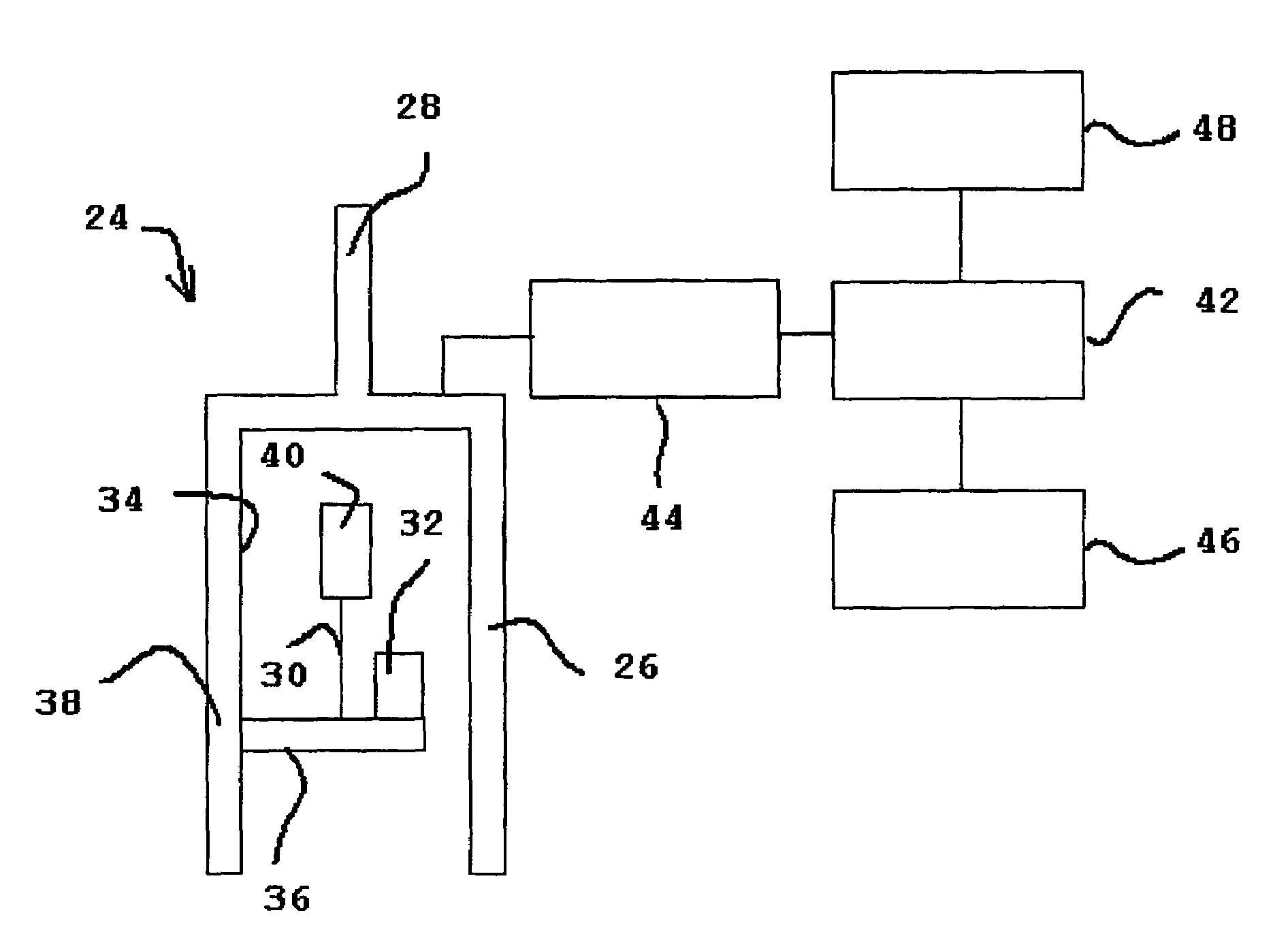
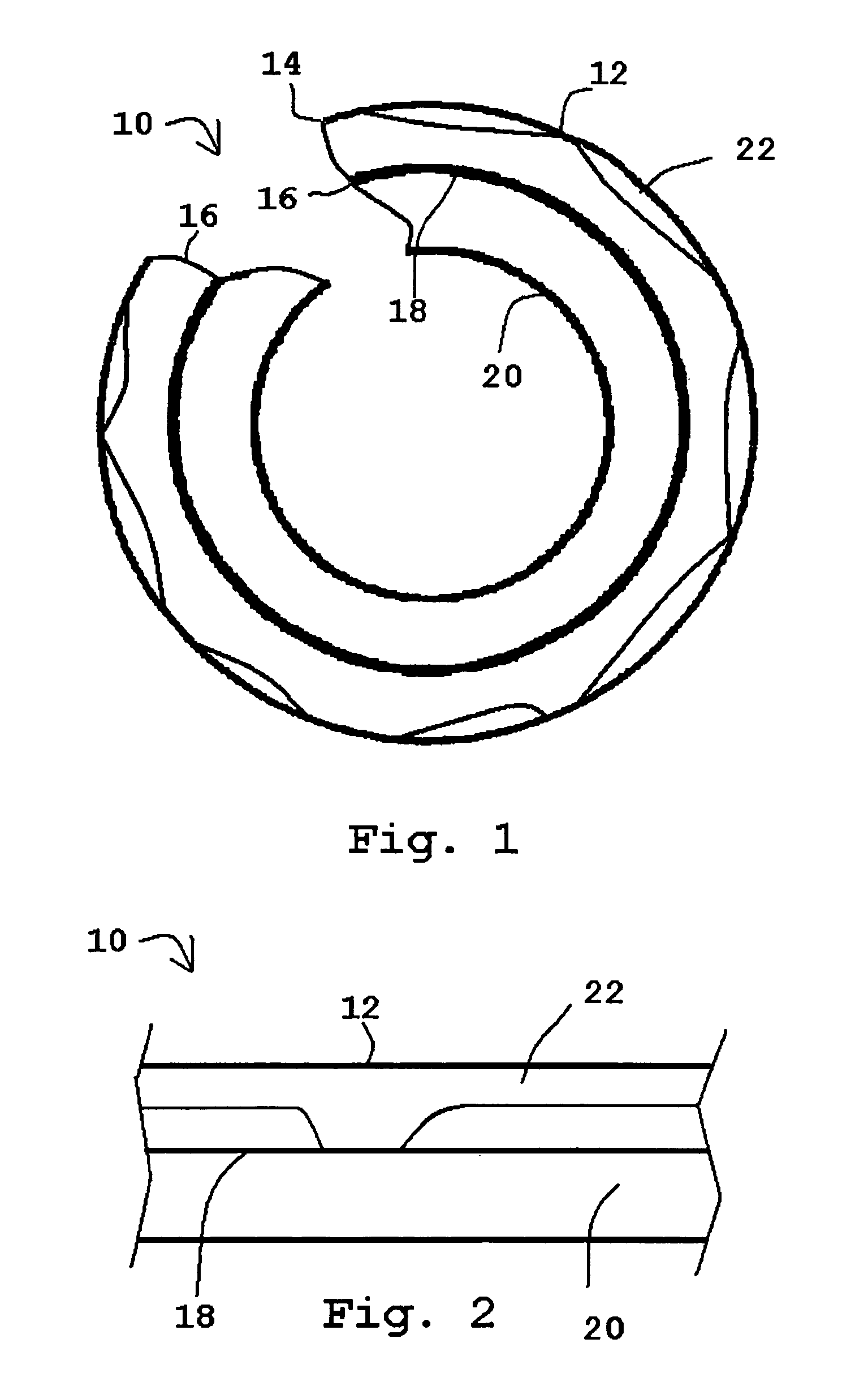
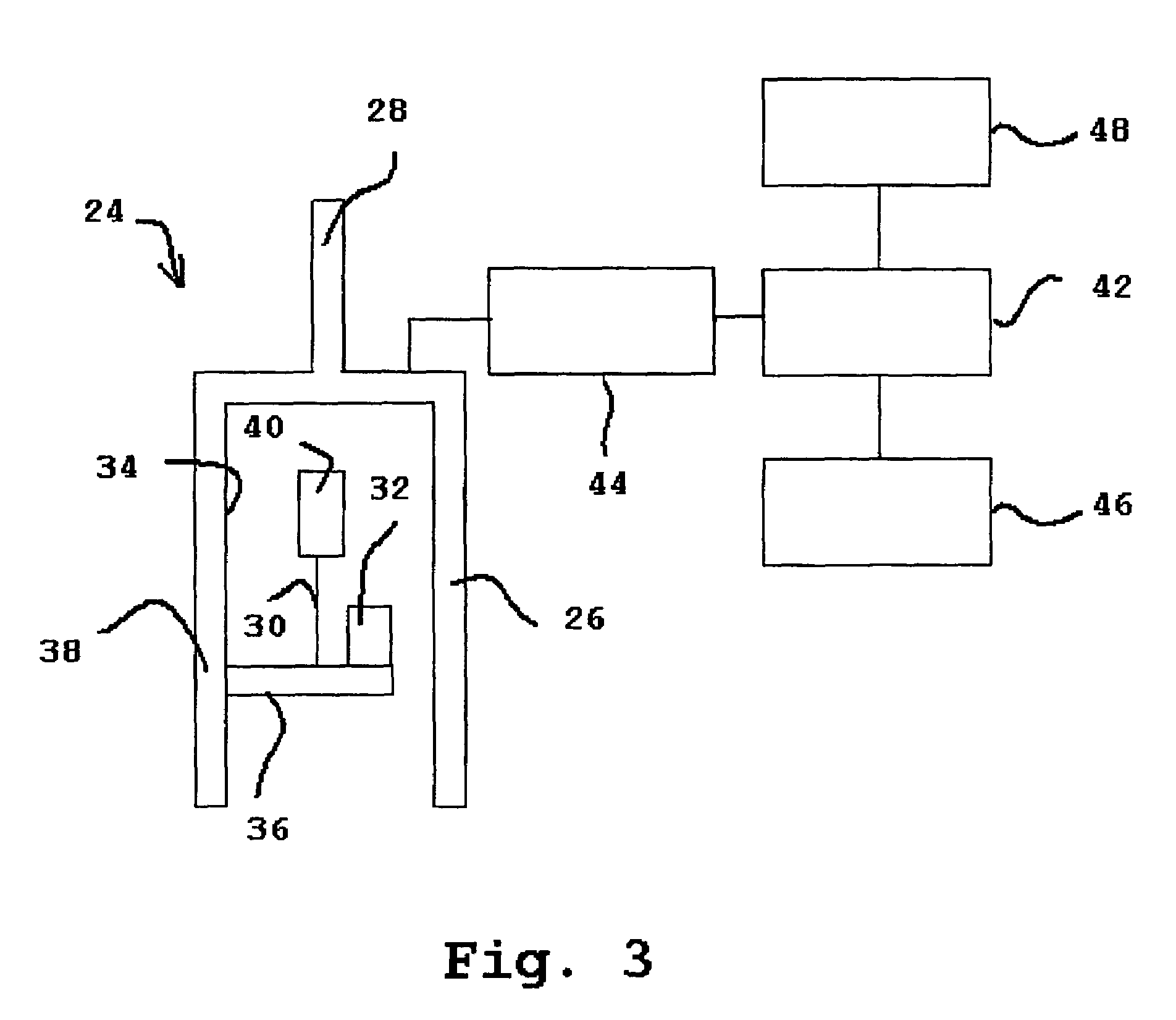
[0034]The present invention is employed with non-destructive testing devices that rely upon measurements of the interaction of magnetic fields with sample surfaces that include magnetic materials. The term “magnetic materials” should be understood to mean materials having ferromagnetic and significant paramagnetic properties. The invention is particularly adapted for detecting graphitization of ferrous alloys, particularly gray iron or ductile iron. The invention is also suitable for detecting other types of localized corrosion phenomena in such samples, as well as localized corrosion phenomena in other materials that include magnetic components.

[0035]The non-destructive testing devices use the magnetic properties of the sample material to determine the homogeneity of regions of the sample surface. Magnetic properties, such as magnetic permeability, magnetic force, and magnetic flux density, provide such devices with the ability to detect graphitic corrosion on gray iron sample surf...


PUM


Abstract

A sensor measures the interaction of an applied magnetic field to a sample surface that includes magnetic materials to determine whether the samples surface has been corroded. The sensor measures the magnetic force resulting from the interaction or the magnetic flux density to determine the content of magnetic material in localized regions of the sample surface. The sensor includes a cantilever beam with a strain gauge for measuring magnetic force. Alternatively, the sensor includes a magnetic flux density sensor to measure magnetic flux density.

Description

BACKGROUND OF THE INVENTION[0001]1. Field of the Invention[0002]This invention relates a method and apparatus for the sensing of magnetic properties and, more particularly, to a non-destructive testing device for detecting graphitization and localized corrosion in gray cast iron, ductile iron, ferrous alloys and other magnetic materials based on magnetic force or magnetic flux density measurements.[0003]2. Description of the Related Art[0004]Water main failures are very expensive for municipalities because they typically result in expenses associated with repair costs, flood damage, and loss of revenue to affected businesses. Water main failures also interrupt the operation of vital services, such as medical care and fire fighting operations. Currently, millions of dollars are spent annually by industry and by municipalities on the repair of failed components of the water distribution infrastructure, such as components that are made from gray cast iron or “gray ironpipe.[0005]The ...

Claims


Application Information

Patent Timeline
IPC IPC(8): G01N27/82
CPCG01R33/1223G01N17/00
Inventor ZAMANZADEH, MEHROOZKIRKWOOD, GORDONSCHEINMAN, SAM
Owner MATCO SERVICES
Learn More