Laminated coil component

a technology of laminated coils and components, applied in the direction of transformers/inductance details, inductances with magnetic cores, inductances, etc., can solve the problems of low magnetic permeability layer contact area and inability to diffuse easily, and achieve the effect of satisfying the direct-current superposition characteristic and preventing the thickness of a layer from functioning

Active Publication Date: 2010-05-18
MURATA MFG CO LTD
View PDF8 Cites 21 Cited by
  • Summary
  • Abstract
  • Description
  • Claims
  • Application Information

AI Technical Summary

Benefits of technology

[0006]To overcome the problems described above, preferred embodiments of the present invention provide a laminated coil component having a satisfactory direct-current superposition characteristic by preventing the thickness of a layer functioning as a non-magnetic layer from being reduced.
[0008]For example, the low-magnetic-permeability layer is preferably made of Zn—Cu ferrite or a non-magnetic material, for example, and the high-magnetic-permeability layers are preferably made of Ni—Zn—Cu ferrite or Ni—Zn ferrite, for example. The low-magnetic-permeability layer may preferably include a plurality of sub-layers, and among the low-magnetic-permeability sub-layers of this multilayer structure, sub-layers that are in contact with the high-magnetic-permeability layers may preferably include pores. Alternatively, two or more of the low-magnetic-permeability layers may be provided in the laminate. In addition, when the pores are filled with a resin, the strength of the laminate is improved.
[0011]In the laminated coil component according to the second preferred embodiment of the present invention, by providing pores in the magnetic layers that are in contact with the non-magnetic layer, the contact area between the non-magnetic layer and each of the magnetic layers is decreased, and Ni in the magnetic layers does not readily diffuse into the non-magnetic layer during firing.
[0012]According to preferred embodiments of the present invention, by providing pores in a low-magnetic-permeability layer or by providing pores in a magnetic layer that is in contact with a non-magnetic layer, a reduction in the thickness of a layer functioning as the non-magnetic layer can be prevented, and thus, a laminated coil component having a satisfactory direct-current superposition characteristic can be obtained.

Problems solved by technology

Furthermore, by providing pores in the low-magnetic-permeability layer, the contact area between the low-magnetic-permeability layer and another layer is decreased, and Ni in the high-magnetic-permeability layer does not readily diffuse into the low-magnetic-permeability layer during firing.

Method used


Image

  • Laminated coil component
  • Laminated coil component
  • Laminated coil component

Examples


first preferred embodiment

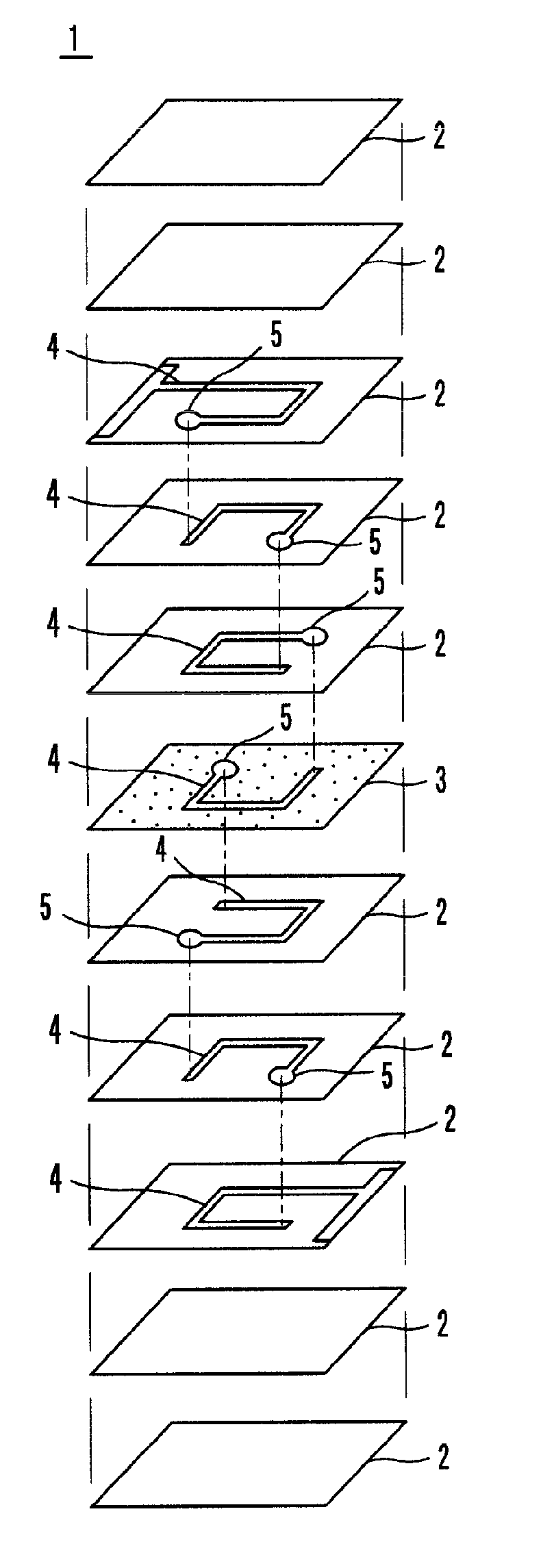
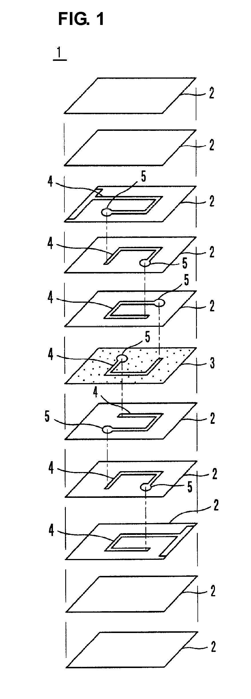
[0025]FIG. 1 shows the exploded structure of a laminated coil component 1 of a first preferred embodiment of the present invention. In the laminated coil component 1, ferrite sheets 2 in which a coil conductor 4 is provided on a surface thereof, ferrite sheets 2 in which no coil conductor is provided on a surface thereof, and a ferrite sheet 3 in which a coil conductor 4 is provided on a surface thereof are laminated.

[0026]Each of the ferrite sheets 2 is a high-magnetic-permeability ferrite sheet and is preferably made of a magnetic material such as Ni—Zn—Cu ferrite or Ni—Zn ferrite, for example. The ferrite sheet 3 is a low-magnetic-permeability ferrite sheet and is preferably made of a non-magnetic material such as Zn—Cu ferrite, for example. The low-magnetic-permeability ferrite sheet 3 is preferably prepared by adding commercially available spherical polymer particles (burn-out material) to Zn—Cu ferrite so that the ferrite sheet 3 has a predetermined porosity after firing, perf...

second preferred embodiment

[0040]FIG. 6 shows a vertical cross section of a laminated coil component 21 of a second preferred embodiment of the present invention. In the laminated coil component 21, a low-magnetic-permeability ferrite layer 23 having a three-layer structure is provided, instead of the low-magnetic-permeability ferrite layer 3 in the laminated coil component 1 of the first preferred embodiment.

[0041]As shown in the enlarged schematic cross-sectional view of FIG. 7, the low-magnetic-permeability ferrite layer 23 is prepared by laminating low-magnetic-permeability ferrite sub-layers 23b including pores 15 or pores 15 filled with a resin on both main surfaces of a low-magnetic-permeability ferrite sub-layer 23a not including pores 15. The low-magnetic-permeability ferrite sub-layers 23b are in contact with high-magnetic-permeability ferrite layers 2.

[0042]The laminated coil component 21 having the above-described structure has substantially the same function and advantages as those in the laminat...

third preferred embodiment

[0044]FIG. 8 shows a vertical cross-section of a laminated coil component 31 of a third preferred embodiment of the present invention. In the laminated coil component 31, two low-magnetic-permeability ferrite layers 3 are provided in the laminate of the laminated coil component 1 of the first preferred embodiment. As described in the first preferred embodiment, each of the low-magnetic-permeability ferrite layers 3 includes pores 15 or pores 15 filled with a resin. The two low-magnetic-permeability ferrite layers 3 divide a high-magnetic-permeability ferrite region in the sintered body 10 into three portions.

[0045]The laminated coil component 31 having the above-described structure has substantially the same function and advantages as those in the laminated coil component 1 of the first preferred embodiment. Furthermore, since a plurality of low-magnetic-permeability ferrite layers 3 are provided in the laminate, the direct-current superposition characteristic is improved.


PUM

PropertyMeasurementUnit
dielectric constantaaaaaaaaaa
magnetic-permeabilityaaaaaaaaaa
non-magneticaaaaaaaaaa

Abstract

A laminated coil component includes high-magnetic-permeability ferrite layers that are disposed on both main surfaces of a low-magnetic-permeability ferrite layer. Pores or pores filled with a resin are formed in the low-magnetic-permeability ferrite layer. Nickel in the high-magnetic-permeability ferrite layers does not significantly diffuse into the pores or the pores filled with the resin during firing, and thus, Ni does not readily diffuse into the low-magnetic-permeability ferrite layer.

Description

BACKGROUND OF THE INVENTION[0001]1. Field of the Invention[0002]The present invention relates to a laminated coil component, and in particular, to an open-magnetic-circuit-type laminated coil component.[0003]2. Description of the Related Art[0004]Japanese Unexamined Patent Application Publication No. 2001-44037 describes an open-magnetic-circuit-type laminated coil component in which a magnetic layer is provided on both main surfaces of a non-magnetic layer to improve the direct-current superposition characteristic. However, when the non-magnetic layer and the magnetic layers are fired in a laminate, Ni included in the magnetic layers diffuses into the non-magnetic layer. More specifically, the non-magnetic layer is made of Zn—Cu ferrite and the magnetic layers are made of Ni—Zn—Cu ferrite or Ni—Zn ferrite, and thus, Ni included in the magnetic layers diffuses into the non-magnetic layer. Consequently, the non-magnetic layer into which Ni is diffused becomes a magnetic material, and...

Claims


Application Information

Patent Timeline
Patent Type & Authority Patents(United States)
IPC IPC(8): H01F5/00
CPCH01F17/0013H01F17/04H01F2017/048
Inventor IWASAKI, TOMOHIDE
Owner MURATA MFG CO LTD
Why Eureka
Try Eureka