Position-detecting mechanism and position-detecting sensor

a technology of position detection and sensor, which is applied in the field of position detection mechanism and position detection sensor, can solve the problems of inaccurate measurement the error of applying the ruler to the sensor, and the large amount of calibration work, so as to achieve the effect of safe and accurate measurement, easy calibration, and convenient judgment of the position of the subject of measuremen

Active Publication Date: 2010-05-18
JUSTIN CO LTD +1
View PDF5 Cites 10 Cited by
  • Summary
  • Abstract
  • Description
  • Claims
  • Application Information

AI Technical Summary

Benefits of technology

[0014]The advantages offered by the first feature of the present invention are as follows. Because the light-emitting means emits a beam of visible light, the spot lit up by the beam on the subject of measurement is visible to the operator. Accordingly, the operator can judge the position of the subject of measurement by the position of the spot on the subject of measurement. Besides, because the beam is regulated so that its cross section will be in a certain shape at the place of the subject of measurement and the cross-sectional area of the beam at the place of the subject of measurement is such that the change of the shape of the spot lit up by the beam on the subject of measurement is visible, the operator can judge the position of the subject of measurement just by checking the shape of the spot lit up by the beam on the subject of measurement. Thus, the operator can easily judge the position of a subject of measurement by using his eyes alone without using a scale. The operator can easily, safely judge the position of a subject of measurement even while it is running on its production line. If the position-detecting mechanism is incorporated into a position-detecting sensor, the operator can judge the deviation of a subject of measurement from the reference line of the position-detecting sensor by using his eyes alone. Therefore, the position-detecting sensor can be calibrated easily, accurately.
[0015]The advantage offered by the second feature of the present invention is as follows. With the position-detecting mechanism, the operator can judge the relative positions of the reference line of the position-detecting mechanism and a subject of measurement.
[0016]The advantage offered by the third feature of the present invention is as follows. Because the light-emitting means is a light-emitting diode, it consumes a small amount of electric power and its service life is long. Thus, its maintenance and running costs are low.
[0017]The advantage offered by the fourth feature of the present invention is as follows. Because the operator can judge the relative positions of the reference line of the position-detecting sensor and a subject of measurement, he can easily, accurately calibrate the position-detecting sensor.
[0018]The advantage offered by the fifth feature of the present invention is as follows. Because the transmitting means serves as the position-detecting mechanism, it is not necessary to provide the position-detecting mechanism in addition to the transmitting means. Thus, the structure of the position-detecting sensor can be simple and the position-detecting sensor itself can be compact.

Problems solved by technology

The operator applies a ruler to the sensor to put its center exactly on one side of a web based on the reading on the ruler; accordingly, there may occur an error in applying the ruler to the sensor.
A plurality of said position-detecting devices are arranged along the right and left sides of a web running through a production line, and every position-detecting device's sensor has to be calibrated for a correct reference value; thus, the calibration work takes a good deal of labor and time.
Besides, if the centers of sensors come off the sides of the web due to vibrations, etc., the operator has to put them back into their places by applying a ruler while the production line is being operated; thus, the position-correcting work takes a great deal of labor and time.

Method used


Image

  • Position-detecting mechanism and position-detecting sensor
  • Position-detecting mechanism and position-detecting sensor
  • Position-detecting mechanism and position-detecting sensor

Examples


Embodiment Construction

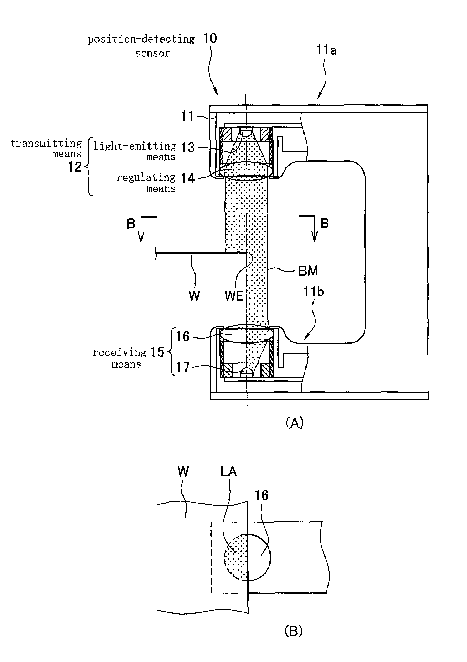
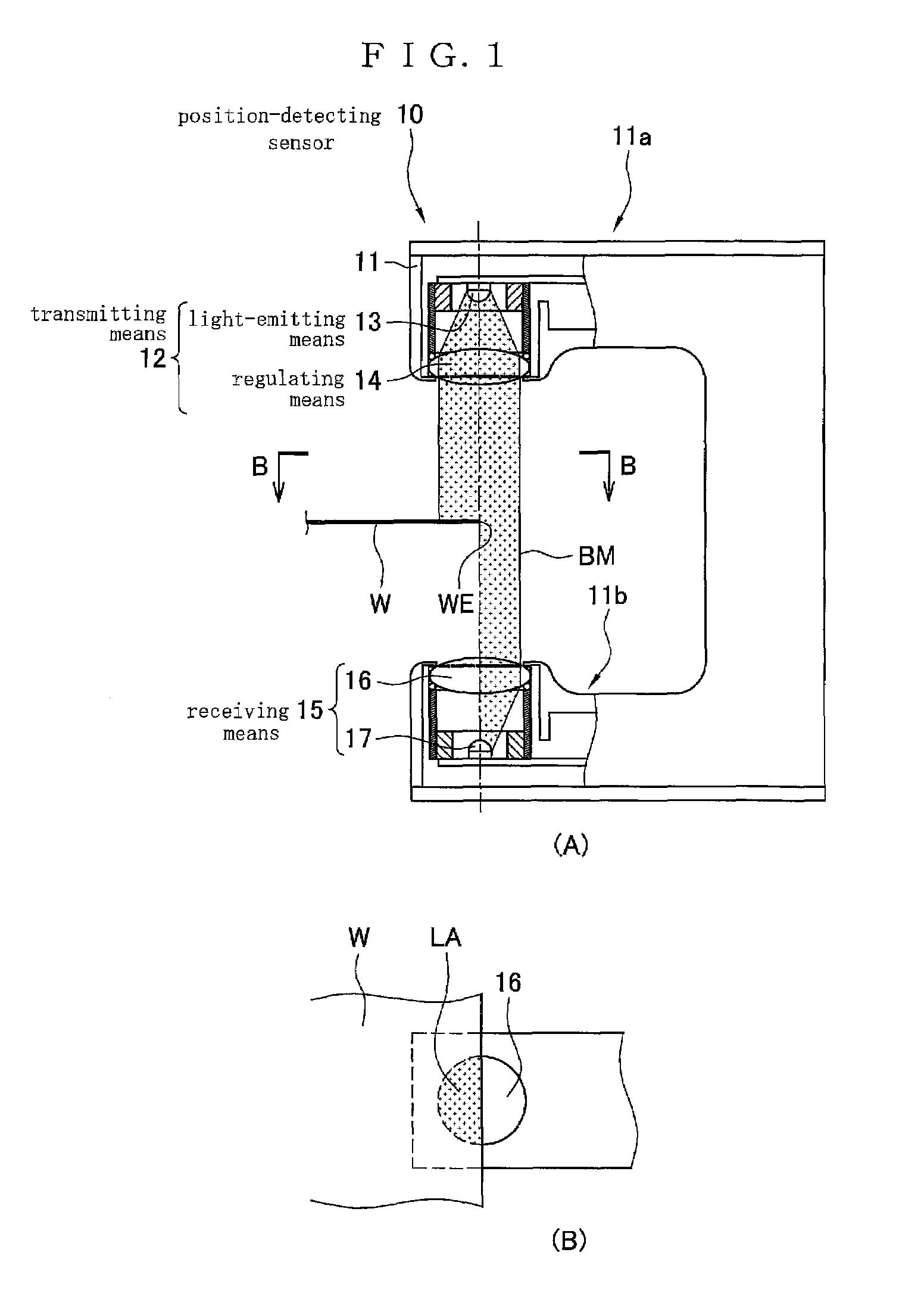
[0025]A preferred embodiment of the position-detecting sensor of the present invention will be described below by referring to drawings.

[0026]The position-detecting sensor of the present invention is to detect the position of a subject of measurement and comprises a position-detecting mechanism capable of detecting the slippage of the subject of measurement from the reference line of the position-detecting sensor.

[0027]Subjects of measurement are webs or the like of paper, nonwoven fabric, film, sheet steel, etc. The position-detecting sensor of this embodiment is suitable especially for detecting the positions of the right and left sides of a web running on a production line. Described below is a web-guiding device which includes the position-detecting sensor of this embodiment to prevent a web running on a production line from meandering.

[0028]Before the position-detecting sensor is described, the web-guiding device will first be described.

[0029]FIG. 4 is a schematic plan view of ...


PUM


Abstract

This invention provides a position-detecting mechanism and a position-detecting sensor, the calibration of the sensor easy, the deviation of a web from the reference line of the sensor easy to find. The position-detecting mechanism comprises (i) a light-emitting means 13 to emit a beam of visible light to a subject of measurement and (ii) a regulating means 14 to regulate the beam so that its cross section will be in a certain shape at the place of the subject of measurement and detects the position of the subject of measurement. Because the light-emitting means 13 emits a beam of visible light, the spot lit up by the beam on a subject of measurement is visible to the operator. Accordingly, the operator can judge the position of the subject of measurement by using his eyes alone without using a scale and easily, safely judge its position even while it is running on its production line.

Description

[0001]This application was filed as PCT application No. PCT / JP2004 / 004116, filed Mar. 24, 2004.TECHNICAL FIELD[0002]This invention relates to a position-detecting mechanism and a position-detecting sensor. When a web of paper, nonwoven fabric, film, sheet steel, or the like runs on its production line, it may meander due to imbalance among rollers, malalignment of reels, or the like. Such meandering may reduce the production speed and cause defective webs to be produced. To rectify such meandering, web-guiding devices are known, which detect the positions of the right and left sides of a web and adjust the position of the web in accordance with the detected positional slippage of the right and left sides. Therefore, it is important for the web-guiding devices to detect the positions of the sides of webs accurately.[0003]This invention relates to a position-detecting mechanism and a position-detecting sensor to detect the positions of the sides of webs.BACKGROUND ART[0004]The Japanes...

Claims


Application Information

Patent Timeline
Patent Type & Authority Patents(United States)
IPC IPC(8): G01B11/14B65H23/02B65H23/032G01D5/32G01D5/34
CPCB65H23/0216G01D5/342G01D5/341G01D5/32
Inventor NAKAYASHIKI, HIROSHI
Owner JUSTIN CO LTD
Why Eureka
Try Eureka