
Image processing apparatus, method, and program, and program storage medium

a technology of image processing and program storage, applied in the field of onlinear, can solve the problems of difficult image searching work by scrubbing, degraded response property for displaying, and inability to realize fast random playback with ease, etc., and achieves easy editing work, easy search, and easy editing work

Inactive Publication Date: 2010-05-18
SONY CORP
View PDF16 Cites 54 Cited by
  • Summary
  • Abstract
  • Description
  • Claims
  • Application Information

AI Technical Summary

Benefits of technology

Facilitates easy editing by enabling quick frame searching and synchronization, improving user experience and efficiency in nonlinear editing.

Problems solved by technology

However, searching for a desired frame (hereinafter, referred to as image searching work) by scrubbing is not easy for unskilled users.
In addition, in a case of long-GOP MPEG clips, in which one Group of Pictures (GOP) has a plurality of frames because of improvement of compression efficiency, or open-GOP clips, in which a frame has been compressed by using frames before and after the frame, some neighboring frames or GOPs need to be decoded to decode a frame, which may not realize fast random playback with ease.
Thus, response property for displaying degrades and the image searching work by scrubbing is not user-friendly.
This means that this cut editing takes some steps, which is not user friendly.
Therefore, video / audio synchronization editing may not be done with ease.

Method used


Image

  • Image processing apparatus, method, and program, and program storage medium
  • Image processing apparatus, method, and program, and program storage medium
  • Image processing apparatus, method, and program, and program storage medium

Examples


first embodiment

(1) First Embodiment

(1-1) Configuration of Editing System 20 According to the First embodiment

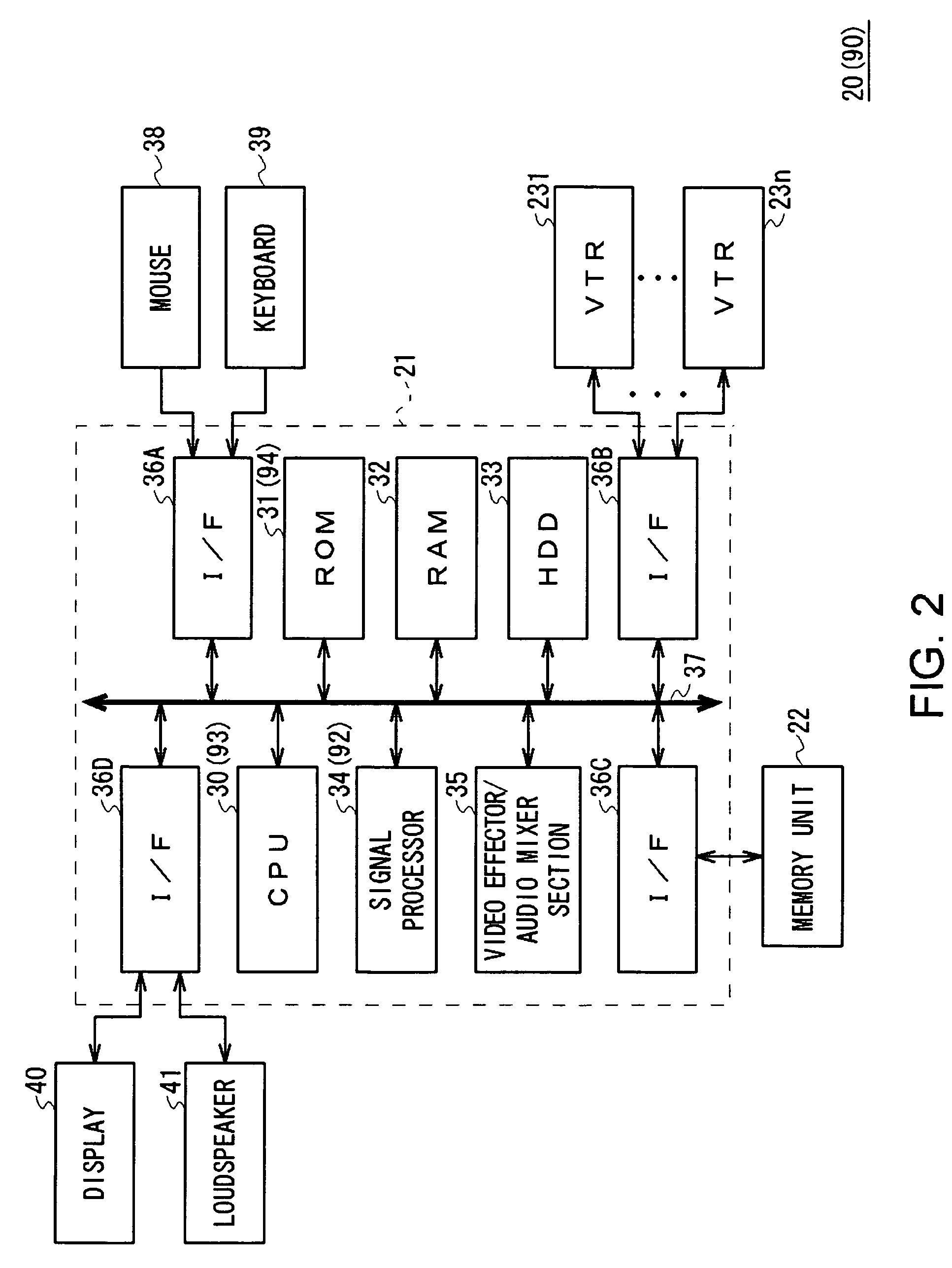
[0053]Referring to FIG. 2, reference numeral 20 shows an editing system according to one embodiment of this invention, and is designed to be capable of importing all or part of video and audio recorded on a video tape as a clip into a large-capacity memory unit 22 which is a redundant-arrays-of-independent-disk (RAID) unit, via an editing apparatus 21.

[0054]This editing system 20 is also designed to be capable of creating an edit list that specifies how to create desired edited video / audio from clips being stored in the memory unit 22, execute an editing process according to the created edit list, and save the edited video / audio in the memory unit 22 or record it on a video tape.

[0055]This editing system 20 has the editing apparatus 21, the memory unit 22, and plural videotape recorders 231 to 23n.

[0056]The editing apparatus 21 has a Central Processing Unit (CPU) 30, a Read Only Memory (ROM...

second embodiment

(2) Second Embodiment

(2-1) Configuration of Editing System According to Second Embodiment

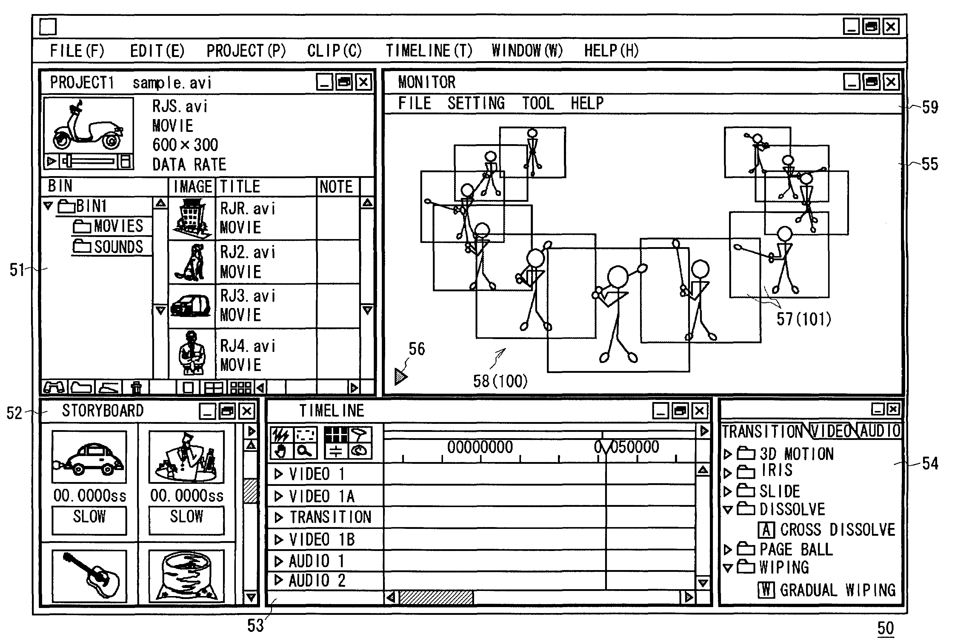
[0281]Referring to FIG. 2, reference numeral 90 shows an editing system according to the second embodiment. This editing system 90 is identical to the editing system 20 (FIG. 2), except that the size of each display area 101 (FIG. 3) of a display area group 100 (FIG. 3) to be displayed on a Workspace window 55 of an edit screen 50 varies depending on a signal level of sound accompanying an image being displayed on the display area 101.

[0282]That is, in this editing system 90, a signal processor 92 of an editing apparatus 91 plays back the clip on each display area 101 of the display area group 100 based on a video / audio signal S4 as shown in FIG. 3, the signal S4 received from a memory unit 22 via a video effector / audio mixer section 35 as described before. In addition, the signal processor 92 sequentially informs a CPU 93 of the peak level of the audio level (signal level of an audio signal S3)...


PUM

PropertyMeasurementUnit
areaaaaaaaaaaa
clock frequencyaaaaaaaaaa
areasaaaaaaaaaa

Abstract

An image processing apparatus, method, and program and program storage medium that enable easy search for a desired part. A plurality of video data are created from video data and are displayed, each as a motion picture, at time intervals in a display order on a plurality of display areas on a display screen.

Description

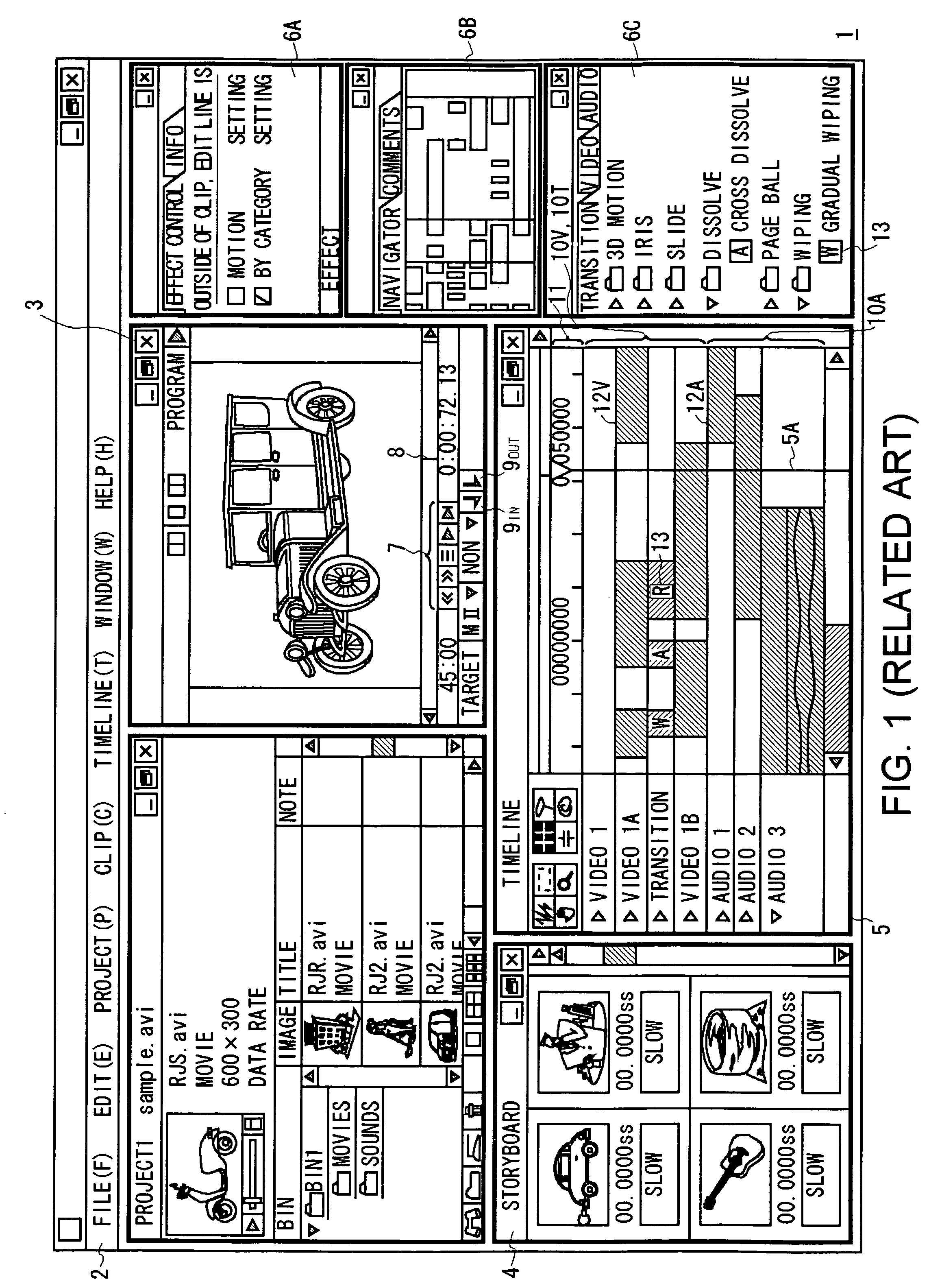
CROSS REFERENCE TO RELATED APPLICATIONS[0001]The present invention contains subject matter related to Japanese Patent Applications JP2004-268939 and JP2005-228656 filed in the Japanese Patent Office on Sep. 15, 2004 and Aug. 5, 2005, respectively, the entire contents of which being incorporated herein by reference.BACKGROUND OF THE INVENTION[0002]1. Field of the Invention[0003]This invention relates to an image processing apparatus, method, and program and a program storage medium, and more particularly to a nonlinear editing apparatus.[0004]2. Description of the Related Art[0005]In workplaces for creating content, such as television broadcasting stations, a single content is created by extracting some parts from video / audio materials (hereinafter, referred to as clips) produced by video cameras, as new clips, and combining them (for example, refer to Japanese Patent Laid-open No. 11-95332).[0006]FIG. 1 shows an example of a graphical User Interface (GUI) screen (hereinafter, referr...

Claims


Application Information

Patent Timeline
Patent Type & Authority Patents(United States)
IPC IPC(8): G11B27/00G11B27/034H04N5/91
CPCG11B27/034H04N5/85G11B27/34G11B27/105H04N5/91
Inventor OGIKUBO, JUNICHI
Owner SONY CORP
Learn More