Calibrated archery bow sight

a technology of bow sight and arcing, applied in the field of archery, can solve the problems of cumbersome and time-consuming archers, inability to use moveable sites on multiple bows, and inability to effectively sight in bows, so as to reduce the effect of vertical arcing displacement, effectively sighting in a bow, and reducing the time-consuming process

Inactive Publication Date: 2010-05-25
YOUNG DANNY L
View PDF24 Cites 12 Cited by
  • Summary
  • Abstract
  • Description
  • Claims
  • Application Information

AI Technical Summary

Benefits of technology

[0005]The current invention fulfills a much needed advance in the art of archery bow sights comprising the manual translation about a vertical arc while in full-draw with a permanent real-world scale disposed on a calibrated range dial. Requiring only two sight-in distances, the presence of a real-world scale provides a visual indication of subsequent calibrated yardage distances, alleviating the time consuming process currently required to effectively sight-in a bow. Using known mathematical principles of trajectory, a fully scaled measurements ranging from distances from ten to one-hundred yards are available to the archer after using the dual sighting process of the current invention. To achieve this, a sliding sight arm allows adjustments to the bow sight to distances closer or further away from the archer's visual perspective to effectively increase or decrease the vertically arced displacement of the sight for ready adaptability to any bow speed. In an alternative embodiment, the device can be outfitted with reference marks showing the correct projected and vertical distance of the sight allowing the device to be transferred to previously sighted bows to provide an accurate sight-in starting location or even eliminating the need to repeat the sighting-in process all together.

Problems solved by technology

This process is repeated for each desired distance and is known by archers to become cumbersome and time consuming, particularly when sighting multiple bows.
Although providing a method for greater accuracy, the presence of multiple sight pins obscures the view of the target and requires the archer to remember the value of each pin while estimating when targets are located between the sighted values.
Therefore, the need for marking each pre-calibrated distance offers little to address the time-expense issue that is much needed in the art.
As a result the moveable-site cannot be used on multiple bows without creating multiple, removable, scaled tapes.

Method used


Image

  • Calibrated archery bow sight
  • Calibrated archery bow sight
  • Calibrated archery bow sight

Examples


Embodiment Construction

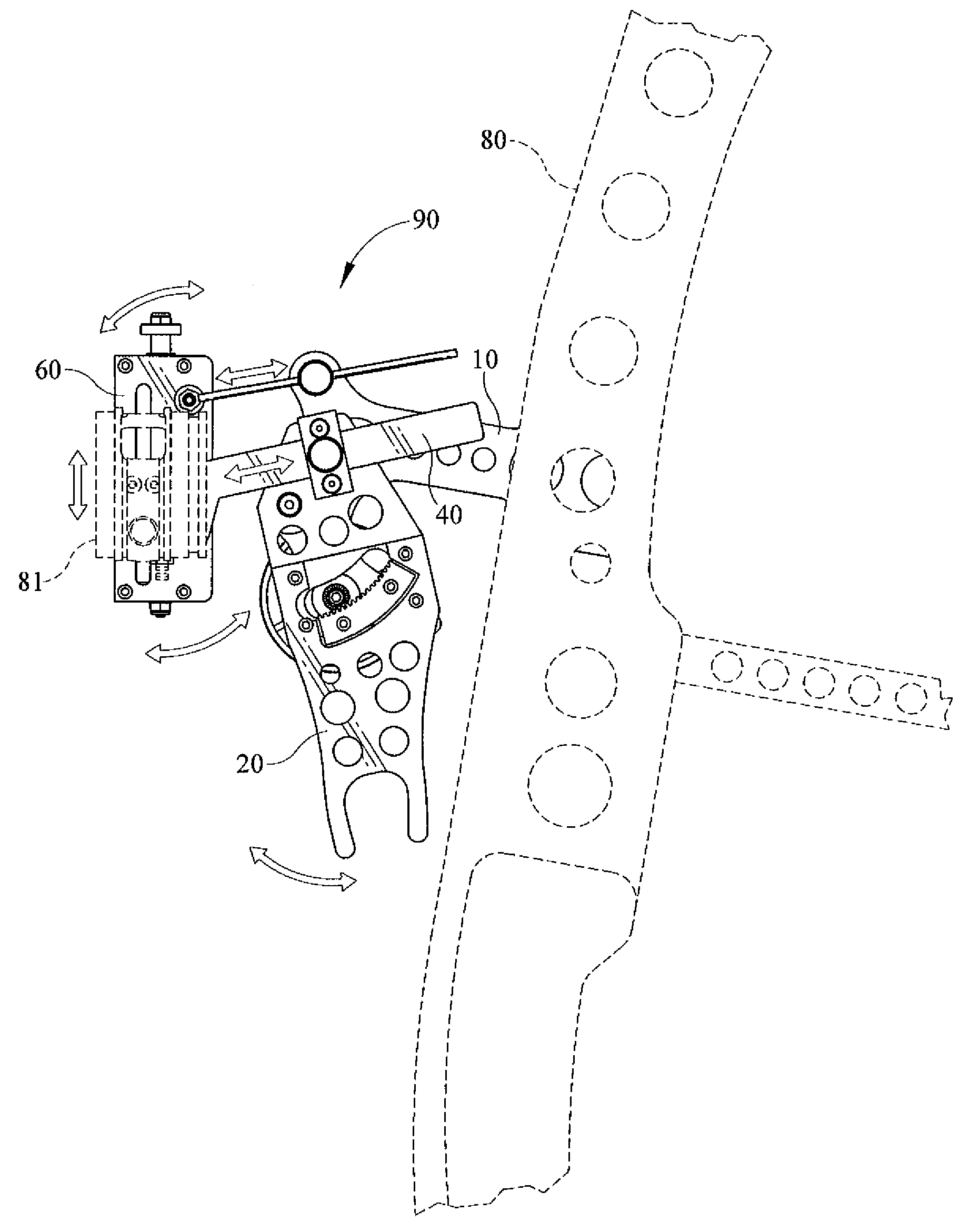
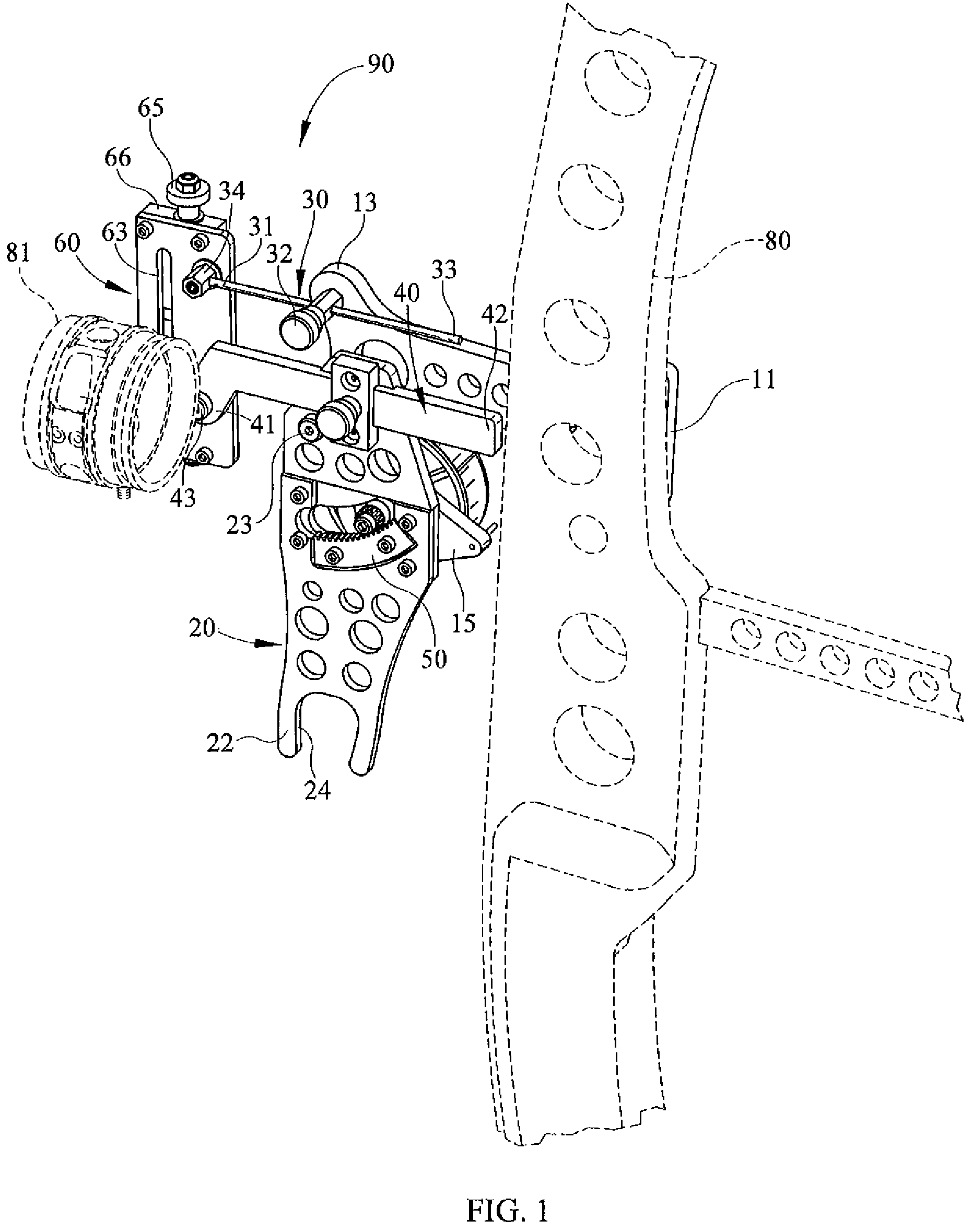
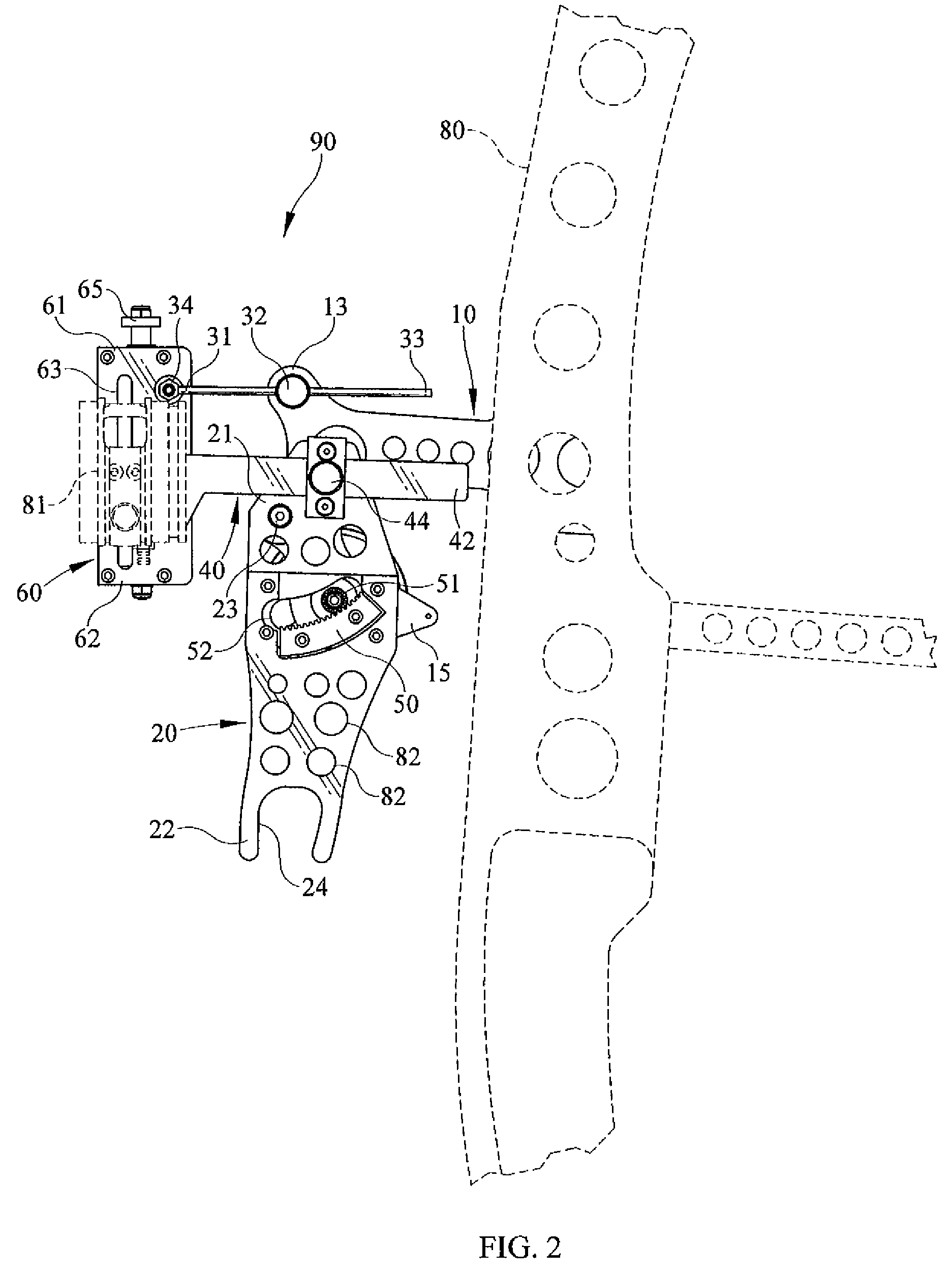
[0013]In the following description, numerous specific details and options of the present invention are set forth in order to provide a more thorough understanding of the claimed invention. It will be appreciated, by one skilled in the art that the Calibrated Archery Bow Sight of the present disclosure may be practiced without such specific details or optional components and that such description are merely for convenience and as such solely selected for the purpose of illustrating the invention. Reference to the figures showing embodiments of the present invention are made to describe the invention and do not limit the scope of the disclosure herein. A calibrated archery bow sight in accordance with the following disclosure is illustrated in the drawings and generally designated 90.

[0014]As shown in FIGS. 4 and 5, the invention 90 is secured with standard fasteners to an archery bow 80 in the general area of the bow riser. The components of the invention 90 include a mounting bracke...


PUM


Abstract

The current invention relates to the need in the art for a bow sighting device that provides accuracy with the versatility that allows the sighting device to be readily transferred to any bow and fully calibrated using minimal sight in distances. From two sight-in yardages, the current invention extrapolates the remaining yardages on a visible scale essentially filling in the gaps using known mathematical principles of trajectory. Vertically arced displacement of a bow sight used in conjunction with the current invention is capable of performing this desirable function on any bow while allowing the archer to manually select a desired range from full draw.

Description

[0001]This application claims priority to Provisional Application 60 / 982,879 filed with the United States Patent and Trademark Office on Oct. 26, 2007.BACKGROUND OF THE INVENTION[0002]In the field of archery, target sights have become as important as the bow itself. Conventional bow sights may include a number of sight pins that are manually set by the archer to sight in the arrow. Sighting requires the archer to make repeated releases toward a target located at a predetermined distance while making fine adjustments to the corresponding sight pin. This process is repeated for each desired distance and is known by archers to become cumbersome and time consuming, particularly when sighting multiple bows. Although providing a method for greater accuracy, the presence of multiple sight pins obscures the view of the target and requires the archer to remember the value of each pin while estimating when targets are located between the sighted values.[0003]Efforts have been made to develop ...

Claims


Application Information

Patent Timeline
Patent Type & Authority Patents(United States)
IPC IPC(8): F41G1/467
CPCF41G1/467
Inventor YOUNG, DANNY L.
Owner YOUNG DANNY L
Why Eureka
Try Eureka