Chain disconnecting and connecting tool

a technology of connecting tool and chain, which is applied in the direction of manufacturing tools, metal chains, assembly machines, etc., can solve the problems of easy deformation of body blocks, difficult to use tools, cumbersome operation, etc., and achieves convenient switching, convenient and compact chain disconnecting and connecting tools, and improved workability.

Inactive Publication Date: 2010-05-25
DAIDO KOGYO CO LTD
View PDF6 Cites 5 Cited by
  • Summary
  • Abstract
  • Description
  • Claims
  • Application Information

AI Technical Summary

Benefits of technology

[0028]According to the first aspect of the invention, the chain disconnecting and connecting tool may be attached to any location on the chain such as the driven sprocket part of the motorcycle from the opening of the tool, and may accommodate several types of motorcycles regardless of a shape of a swing arm and may be attached to a part such as the driven sprocket part where the work may be done readily. Thus, the workability may be improved.
[0035]According to the seventh aspect of the invention, the abutting member is rotatably attached to the distal end portion of the tap bolt, so that when the second block is to be positioned, the tap bolt may be readily rotated while abutting the edge thereof to the second block, may support the load acting on the second block at an adequate position and can steadily prevent the bending moment from acting on the coupling member.

Problems solved by technology

Therefore, there have been cases when the place to which the chain disconnecting and connecting tool is attached is limited, the operation becomes cumbersome or it becomes difficult to use the tool, depending on a shape of a swing arm of the motorcycle.
It is noted that although there also exists a chain disconnecting and connecting tool having a cantilever structure with a body block in a shape of C, this tool has had problems that in terms of durability, the body block is readily deformable due to the cantilever structure and that the tool would be large and heavy and be inconvenient to carry when a robust and highly rigid body block is used.

Method used


Image

  • Chain disconnecting and connecting tool
  • Chain disconnecting and connecting tool
  • Chain disconnecting and connecting tool

Examples


Embodiment Construction

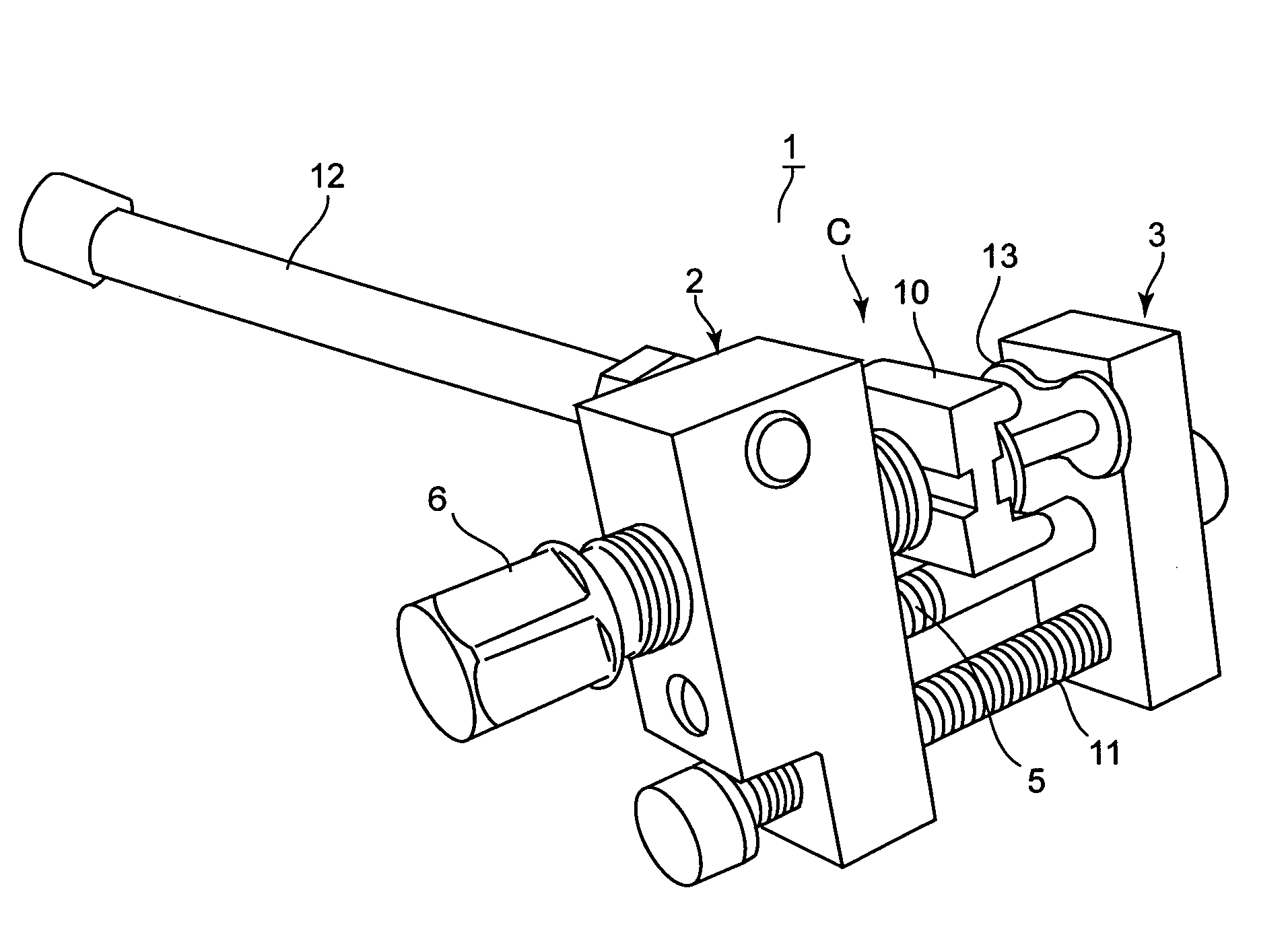
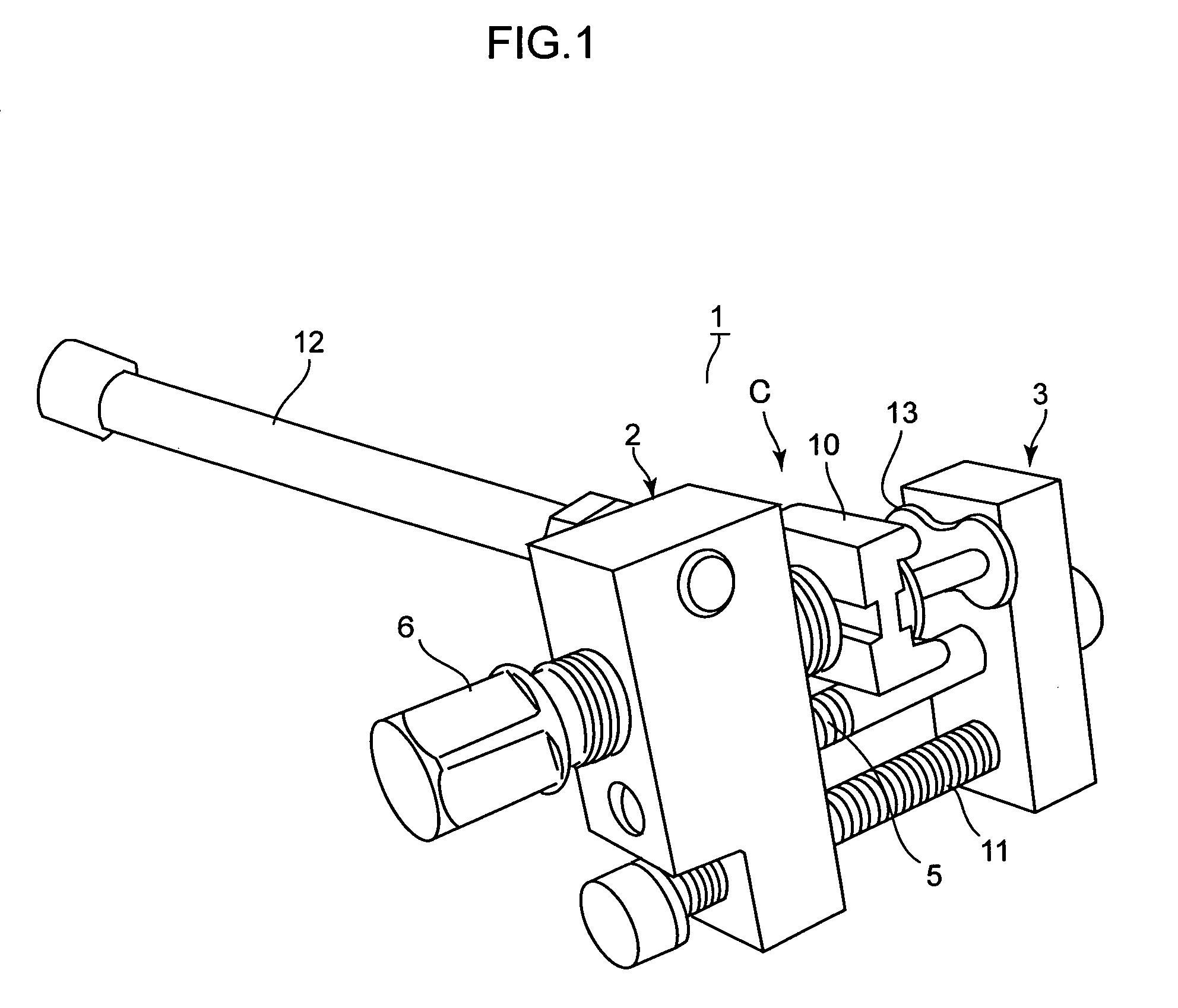
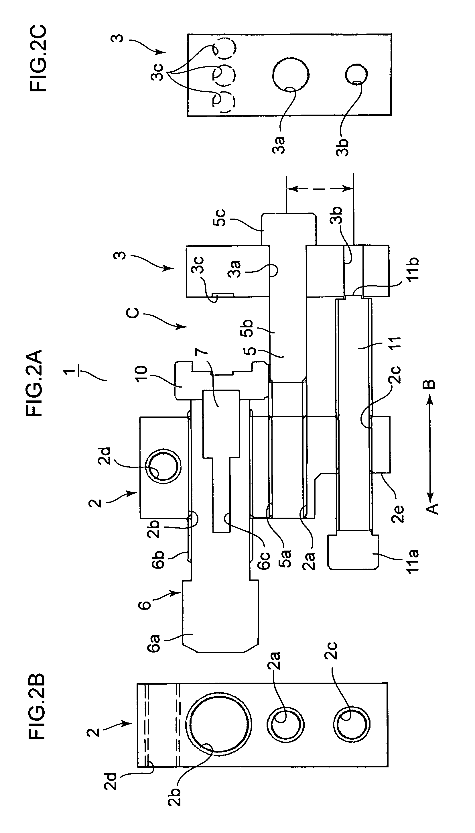
[0042]The invention will now be described based on preferred embodiments and with reference to the drawings, which do not intend to limit the scope of the invention, but exemplify the invention. All of the features and the combinations thereof described in the embodiments are not necessarily essential to the invention. As shown in FIGS. 1 and 2, a chain disconnecting and connecting tool 1 has a first block 2 and a second block 3 made of a metallic material and these both blocks 2 and 3 are coupled by a coupling bolt (link member) 5 substantially at center parts of the blocks. A distal end portion of the coupling bolt 5 is formed into a male screw 5a and is screwed into a screw hole 2a of the first block 2. A base portion of the coupling bolt 5 is formed into a non-screwed round bar 5b and is fitted (received) into a round holder (through hole) 3a of the second block 3 while being retained by a head 5c. Accordingly, the second block 3 is coupled to the first block 2 turnably centerin...


PUM

PropertyMeasurementUnit
pressureaaaaaaaaaa
tensile forceaaaaaaaaaa
compressive forceaaaaaaaaaa

Abstract

A highly durable and compact chain disconnecting and connecting tool that may be used for a chain at a sprocket part for winding the chain and that can receive an operational load at two places is provided. A first block has an engaged pressure actuating member coupling member. A second block is coupled with the first block turnably by the coupling member and has a cutout on one side and a through hole on another side of the block. The tool is attached to the chain from an opening while positioned engagement with an edge projection of a tap bolt that is screwed with the first block and with the cutout or the through hole.

Description

CROSS REFERENCE TO RELATED APPLICATIONS[0001]This application claims the foreign priority benefit under Title 35, United States Code, §119(a)-(d) of Japanese Patent Application No. 2008-105704, filed on Apr. 15, 2008, in the Japan Patent Office, the disclosure of which is herein incorporated by reference in its entirety.BACKGROUND OF THE INVENTION[0002]1. Field of the Invention[0003]The present invention relates to a chain disconnecting and connecting tool for use for chains such as a roller chain for disconnecting the chain by pulling (removing) a pin out of the chain and connecting the chain by caulking (deforming) an end of a pin of a joint link (chain linking member) and more specifically to a chain disconnecting and connecting tool suitably applied to a motorcycle driving roller chain.[0004]2. Related Art[0005]Heretofore, the present applicants have proposed a chain disconnecting and connecting tool as disclosed in Japanese Patent No. 3431361 for example. This tool has first an...

Claims


Application Information

Patent Timeline
Patent Type & Authority Patents(United States)
IPC IPC(8): B21L21/00B23P21/00B25B27/14
CPCB25B27/22B25B27/0071
Inventor KOMEYA, AKIYOSHIHIRASAWA, SUSUMU
Owner DAIDO KOGYO CO LTD
Why Eureka
Try Eureka