High speed rotating atomizer assembly

a rotating atomizer and assembly technology, applied in the direction of electrostatic spraying apparatus, burners, artistic surface treatment, etc., can solve the problems of not providing constant surface to surface contact between the air shaping ring and the turbine device, and no prior art patent teaches an improved design of the atomizer, so as to improve the ionization of the atomized fluid particles and improve the surface-to-surface contact

Active Publication Date: 2010-05-25
DURR SYST INC
View PDF27 Cites 16 Cited by
  • Summary
  • Abstract
  • Description
  • Claims
  • Application Information

AI Technical Summary

Benefits of technology

[0009]An advantage of the present invention is to provide an annular wall that extends outwardly from the turbine device defining a seat for engaging the housing thereby forming a rigidly stabilized connection between the turbine device and the housing, which have proven to maintain a fixed gap between the shaft of the rotational bell unit and the paint line for keeping the shaft at a fixed distance relative to the paint line to prevent contact between the paint line and the shaft.
[0010]Another advantage of the present invention is to provide the turbine device having an improved surface-to-surface contacts between the potential member and the turbine device to improve ionization of the atomized fluid particles.

Problems solved by technology

This design is complex and requires additional component, such as the aforementioned fastener to interconnect the housing with the air shaping ring.
Hence, the air shaping ring and the turbine device taught by the U.S. Pat. No. 6,623,561 to Vetter et al. do not provide for constant surface to surface contact between the air shaping ring and the turbine device.
In addition, none of the prior art patents teaches an improved design of the atomizer having improved rigidly stabilized connection between the turbine device and the housing for maintaining a fixed air gap between the shaft and a paint pipe or line extending through the shaft for keeping the shaft at a fixed distance relative to the paint line as the shaft rotates around the axis.

Method used


Image

  • High speed rotating atomizer assembly
  • High speed rotating atomizer assembly
  • High speed rotating atomizer assembly

Examples


Embodiment Construction

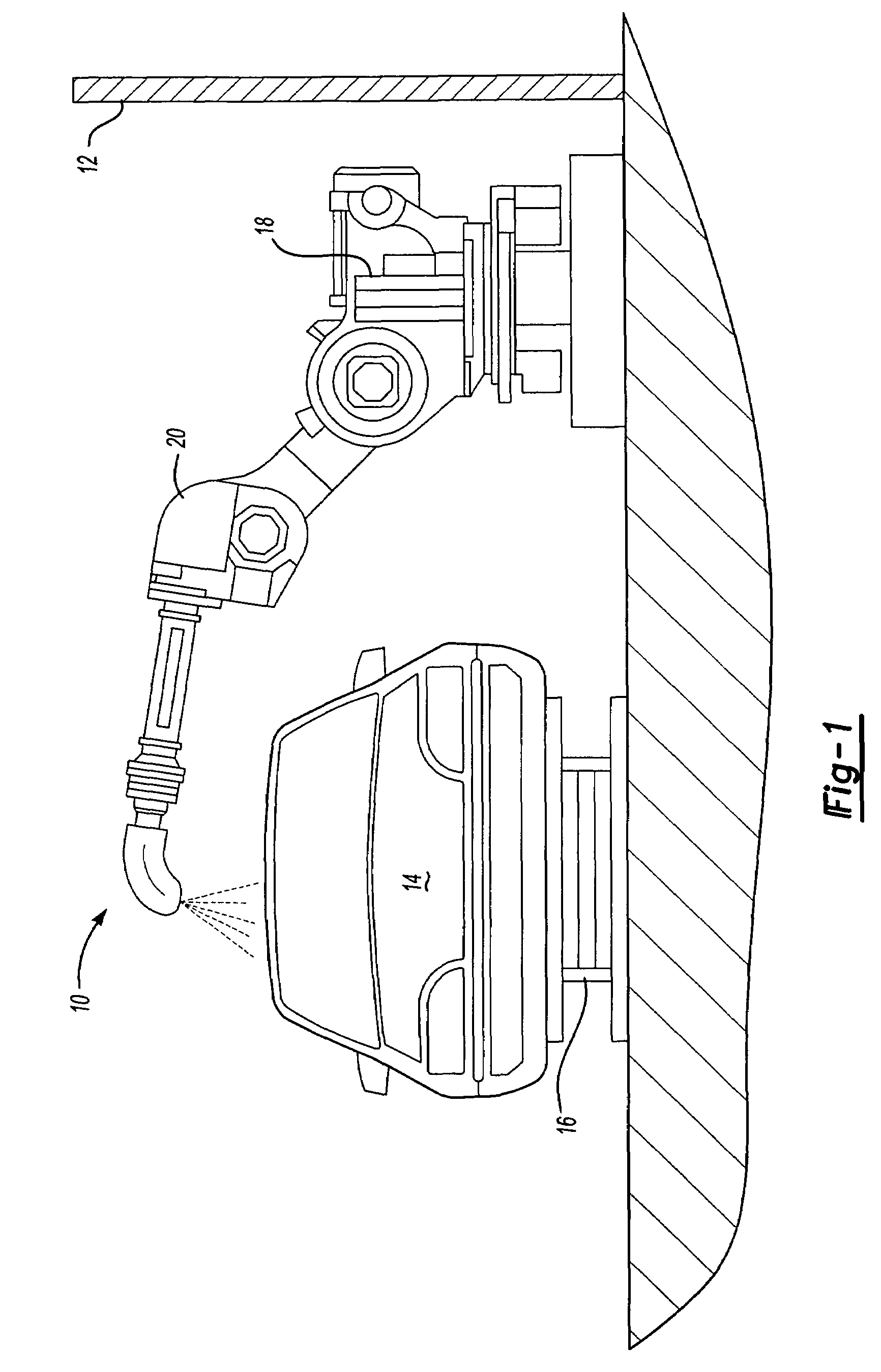
[0020]Referring to the FIGS. 1 and 2, wherein like numerals indicate like or corresponding parts, an inventive atomizer assembly is generally shown at 10. A paint circulation system (not shown) supplies paint to a paint booth 12 where the paint is applied to a production part, such as, for example, a vehicle body 14. In a typical automobile assembly plant the vehicle body 14 is transported through the paint spray booth 12 by conveying equipment 16 where the paint is applied to the vehicle body 14 and subsequently cured in a paint oven (not shown) as is known to those skilled in the art. The paint is applied by automated application equipment, such as a robotic device 18 that includes the atomizer assembly 10 that is connected to an arm 20 of the robotic device 18. Alternatively, the atomizer assembly 10 is operably connected to an overhead or side reciprocator (not shown).

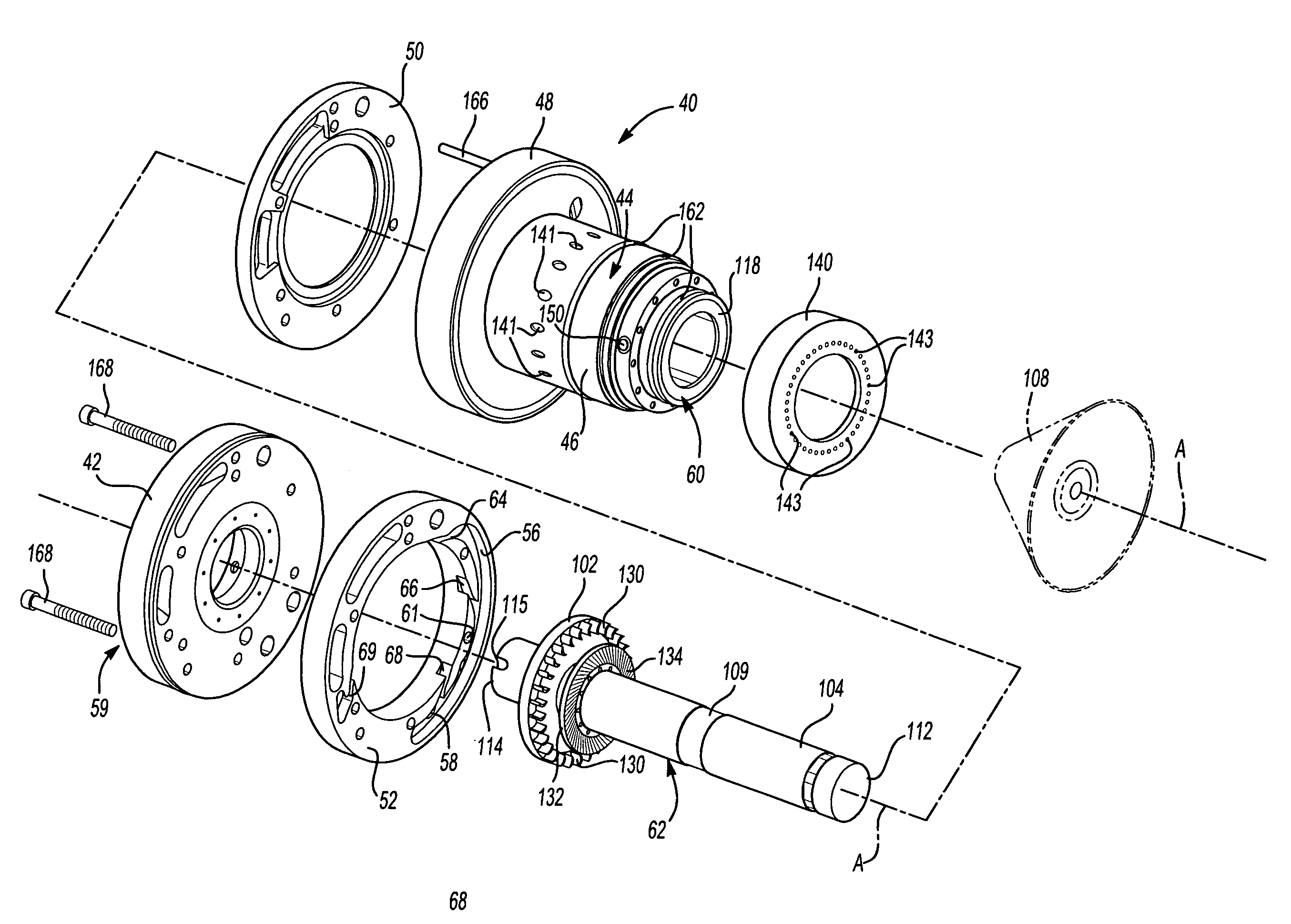
[0021]Referring to FIGS. 2 through 4, the atomizer assembly 10 includes a housing, generally indicated at 22 in ...


PUM


Abstract

An atomizer assembly (10) drives an atomizing bell (108) to apply paint onto a part (14). The atomizer assembly (10) includes a core (24) having at least one paint line (26) extending therethrough, a turbine device (40) circumscribing an axis (A) and disposed in the core (24), and a turbine unit (62) surrounding the pain line (26) and having a shaft (104) rotatable relative the turbine device (40) with several turbine blades (130) connected to the shaft (104). A plurality of nozzles (64, 66, 68) are defined in the turbine device (40) and are positioned relative a turbine wheel (106) connected to the shaft (104) to drive fluid, i.e. gas onto the turbine blades (130). An annular wall (94) extends outwardly from one of the terminal ends of the turbine device (40) to define a seat (96) for engaging the core (24) to maintain a fixed gap between the paint line (26) and the shaft (104) and to eliminate contact therebetween.

Description

RELATED APPLICATION[0001]This application is a continuation in part application of a co-pending patent application Ser. No. 10 / 895,446 filed on Dec. 17, 2003 and an allowed application Ser. No. 10 / 624,586 filed on Jul. 22, 2002, all of which are incorporated herewith by reference.FIELD OF THE INVENTION[0002]This invention relates to a bearing unit of a rotating atomizer for driving a bell cup coupled to the turbine device for coating a part.BACKGROUND OF THE INVENTION[0003]A production paint application process where paint is applied to a substrate, such as, for example a vehicle body moving through a paint booth, requires paint to be transferred from a paint reservoir to a paint applicator robot disposed in the paint booth, where paint is applied by a rotary atomizer as an integral part of the paint applicator robot. Typically, the rotary atomizer includes a turbine device disposed in a housing, a rotating bell unit having a shaft connected to a bell cup and disposed in and rotatab...

Claims


Application Information

Patent Timeline
Patent Type & Authority Patents(United States)
IPC IPC(8): F23D11/04
CPCB05B3/1014B05B5/0415B05B3/1064B05B3/1035B05B3/1092
Inventor NOLTE, HANS J.KRUMMA, HARRYHERRE, FRANKBAUMANN, MICHAELGIULIANO, STEFANOLIND, BJORN
Owner DURR SYST INC
Why Eureka
Try Eureka