Plastic bag sealing device

a sealing device and plastic bag technology, applied in the field of plastic bag sealing devices, can solve problems such as taking up too much space, and achieve the effects of reducing work table space, reducing labor intensity, and increasing economic gain

Inactive Publication Date: 2010-05-25
CHEN CHUN SHAN
View PDF15 Cites 10 Cited by
  • Summary
  • Abstract
  • Description
  • Claims
  • Application Information

AI Technical Summary

Benefits of technology

[0005]The objective of the invention is to offer a plastic bag sealing device able to execute sealing with quickness and with large strength for a plastic bag, combined together with a dot-cutting device and an opening-cutting device to respectively carry out dot-cutting and cutting so as to shrink its work table to greatly elevate economic gain.
[0006]The main characteristics of the invention are a work table, a sealing device fixed on the work table and having a silicon rubber roller, a material intake press roller and a material outlet press roller fixed beside the silicon rubber roller to press thereon, plural rotating shafts fixed outside around the silicon rubber roller and respectively mounted with a sealing blade, plural guide rollers fixed on the work table to conduct plastic bags, a dot-cutting device, a cutting device installed beside the dot-cutting device, and a press roller fixed beside the dot-cutting device and the cutting device. With the sealing blades to carry out multiple sealing at the same location, a plastic bag can be quickly and firmly sealed to step up economic gain, and with the dot-cutting device and the opening-cutting device installed on the work table to respectively execute dot-cutting and cutting, the whole process of manufacturing the plastic bag can be substantially downsized.

Problems solved by technology

In addition, due to being sealed only one time by the sealing blade 17, the sealed location of a plastic bag is insufficient in strength, likely to cause disqualified products; therefore, the conventional plastic bag-sealing machine 1 is only applicable to comparatively thin plastic bags 19.
Moreover, the conventional plastic bag-sealing machine 1 has all its components transversely disposed in a line on the worktable 10, taking too much space.

Method used


Image

  • Plastic bag sealing device
  • Plastic bag sealing device
  • Plastic bag sealing device

Examples


Embodiment Construction

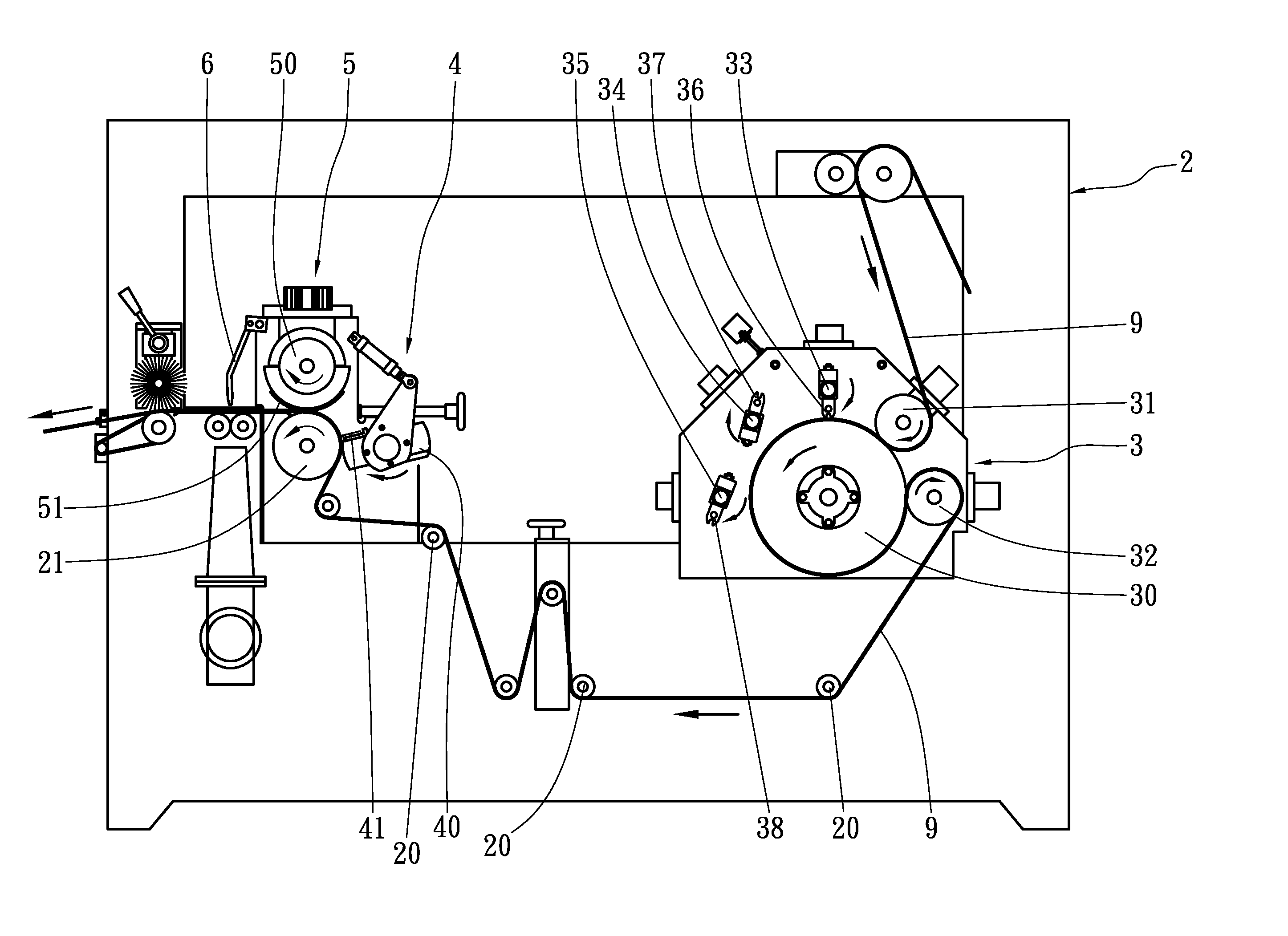
[0017]A preferred embodiment of a plastic bag sealing device in the present invention, as shown in FIGS. 3˜5, includes a work table 2, a sealing device 3 and a dot-cutting device 4 installed on the work table 2, and a cutting device 5 and an air nozzle 6 as main components combined together.

[0018]The sealing device 3 is provided with a silicon rubber roller 30, a material intake press roller 31 and a material outlet press roller 32 installed to press on one side of the silicon rubber roller 30 and properly spaced apart each other. Further, a first rotating shaft 33, a second rotating shaft 34 and a third rotating shaft 35 are fixed outside the silicon rubber roller 30, spaced apart around the other side of the silicon rubber roller 30, and respectively fixed thereon with a first sealing blade 36, a second sealing blade 37, and a third rotating shaft 38. When the first, the second and the third sealing blade 36, 37 and 38 are rotated to contact with the silicon rubber roller 30 in du...


PUM

PropertyMeasurementUnit
plasticaaaaaaaaaa
areaaaaaaaaaaa
distanceaaaaaaaaaa

Abstract

A plastic bag sealing device includes a work table, a sealing device having a silicon rubber roller, a material intake press roller and a material outlet press roller fixed beside the silicon rubber roller to press thereon, plural rotating shafts fixed outside around the silicon rubber roller and respectively mounted with a sealing blade, plural guide rollers employed to conduct plastic bags, a dot-cutting device, an opening-cutting device, and a press roller fixed beside the dot-cutting device and the opening-cutting device. With the sealing blades to carry out multiple sealing at the same location, a plastic bag can be quickly and firmly sealed, and with the dot-cutting device and the opening-cutting device installed on the work table to respectively execute dot-cutting and opening-cutting, the work table can be comparatively downsized, thus greatly elevating economic gain.

Description

BACKGROUND OF THE INVENTION[0001]1. Field of the Invention[0002]This invention relates to a plastic bag sealing device, particularly to one able to carry out multiple sealing at the same sealing location of a plastic bag to achieve a quick and firm sealing work, installed together with a dot-cutting device to cut a dotted line near the sealing location of the plastic bag and with an opening-cutting device to cut an opening for the plastic bag to comparatively downsize a work table of the sealing device, greatly elevating economic gain.[0003]2. Description of the Prior Art[0004]A conventional plastic bag-sealing machine, as shown in FIGS. 1 and 2, includes a worktable 10 provided thereon with a material intake press roller 11. A guide roller 12 is positioned beside the material intake press roller 11, a silicon rubber roller 13 is provided near the guide roller 12, and a material outlet guide roller 14 is disposed beside the silica gel roller 13. A sealing device 15 is positioned opp...

Claims


Application Information

Patent Timeline
Patent Type & Authority Patents(United States)
IPC IPC(8): B31B1/64B31B50/64B31B50/16
CPCB26D1/405B29C66/4312B26F1/384B29C65/7457B29C66/232B29C66/81457B29C66/83411B29C66/83415B29C66/83511B31B19/16B31B19/64B31B23/00B29C65/74B29C66/21B29C66/8511B29C66/91445B29C2793/0045B29C2793/009B29K2883/00B31B2219/14B31B2219/145B31B2219/603B31B2237/10B31B2237/60B26F1/20B29C65/00B29C66/8122B29C66/1122B31B70/00B31B2160/10B31B70/14B31B70/16B31B70/64B31B2155/00B31B2155/003
Inventor CHEN, CHUN-SHAN
Owner CHEN CHUN SHAN
Why Eureka
Try Eureka