Method for sterile connection of tubing

a technology of flexible polymeric tubing and connection method, which is applied in the direction of non-rigid containers, synthetic resin layered products, packaging, etc., can solve the problems of two products not being able to sterilize in the same way, the balance of water, minerals and daily metabolic load cannot be achieved, and the level of sterilization cannot be achieved

Inactive Publication Date: 2010-05-25
BAXTER INT INC
View PDF261 Cites 19 Cited by
  • Summary
  • Abstract
  • Description
  • Claims
  • Application Information

AI Technical Summary

Problems solved by technology

One example in the medical context is when two flowable medical products (e.g., liquids and mixtures of liquids and solids) need to be delivered to the patient at the same time, but the two products cannot be sterilized in the same way.
This is expensive and may not lead to a level of sterilization in the final product which is superior to making and packaging the products in a nonsterile environment and subsequently sterilizing both the products and the package.
However, this requires a sterile connection of the packages, and more specifically a sterile connection of tubes connected to the packages.
The balance of water, minerals and the excretion of daily metabolic load is no longer possible in renal failure.
During renal failure, toxic end products of nitrogen metabolism (urea, creatinine, uric acid and others) can accumulate in blood and tissues.
However, by and large, these connections and disconnections are performed manually.
These devices have a relatively low level of reliability due to the inconsistency in melting and cutting processes.
The inconsistency of operation can result in imperfect seals, leading to leaks, and bacterial infiltration which may lead to infection or peritonitis.
This can lead to contamination of the tube ends, and ultimately of the interior of the tubes, even if the device works perfectly.
The interior passages of the tubing sections are initially sterile, but cutting the tubing sections so that connections of adjacent sections can be made exposes the interior passages of the tubing sections to the surrounding environment, allowing them to potentially become contaminated with airborne contaminants, e.g., bacteria.
Moreover, if the tubing sections are open, solid material from the unsterile exteriors of the tubing sections could enter the tubing sections.
In the applications just described, it is impractical to engage in a resterilization procedure every time a new connection of tubing sections is made.
In time, however, the heated blade or other surface becomes fouled with the plastic material of the tube, requiring cleaning to maintain operability.
One drawback of these systems is that a substantial amount of power is required heat the end portions of the tubing sections.
The conventional medical tubing material does not absorb the energy of the electromagnetic radiation well, so considerable energy is required to melt the tubing.
Moreover, these methods have still required heating, followed by movement of the tubing sections into engagement.

Method used


Image

  • Method for sterile connection of tubing
  • Method for sterile connection of tubing
  • Method for sterile connection of tubing

Examples


Embodiment Construction

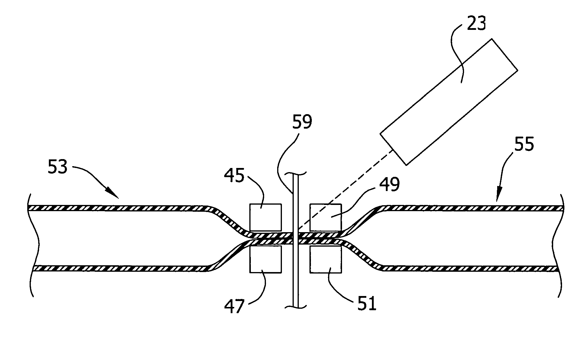
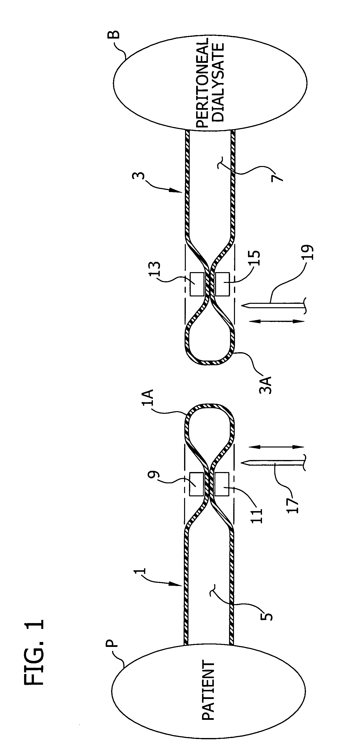
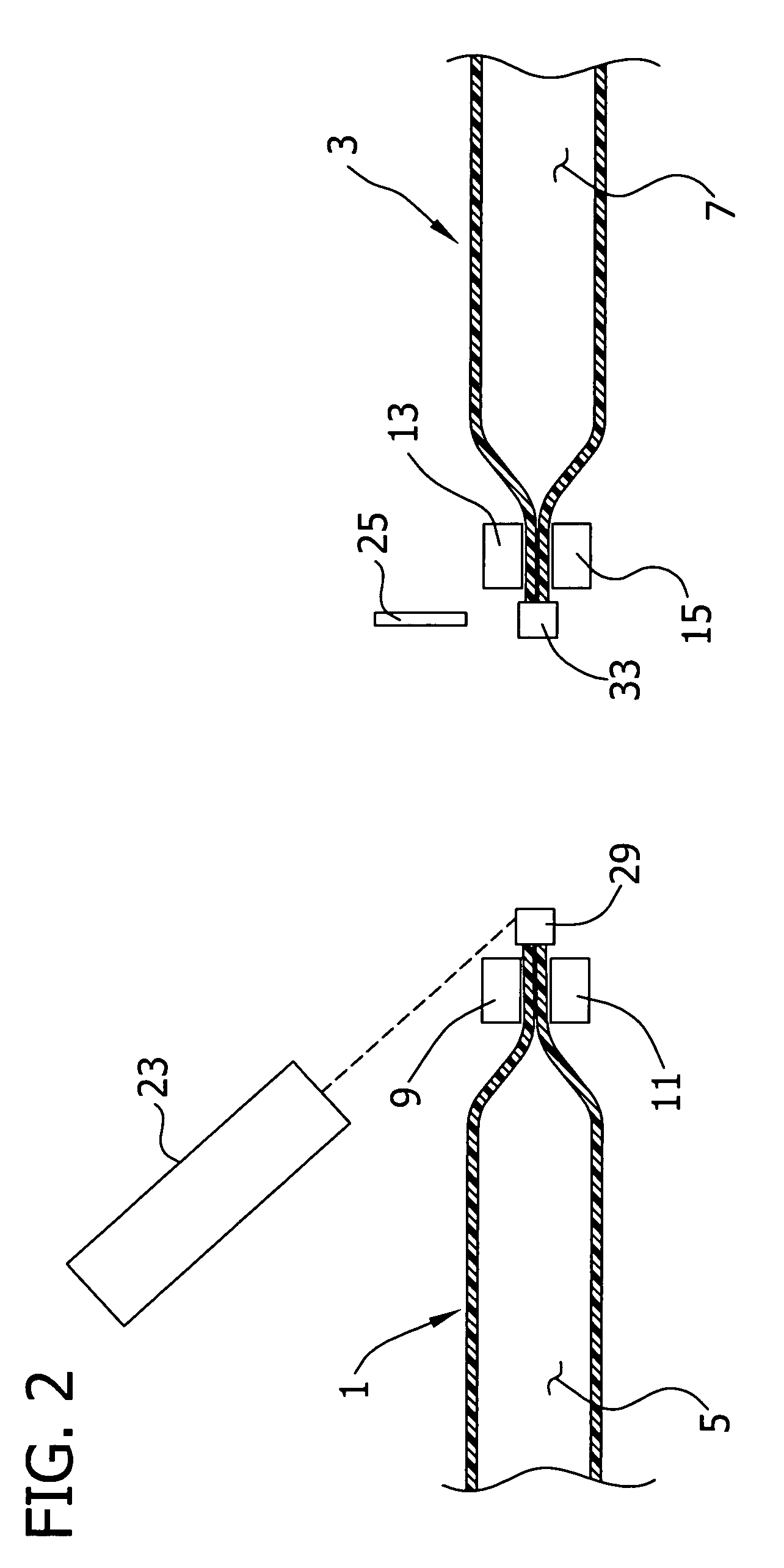
[0034]Referring now to the drawings and in particular to FIGS. 1-8, a method and apparatus for connecting two tubing sections are schematically illustrated. The tubing sections (designated generally at 1 and 3, respectively) are shown as having closed end portions 1A and 3A. The present invention has particular, although not exclusive, application where it is important to keep the interior passages (5 and 7, respectively) of the tubing sections 1, 3 sterile or substantially sterile while connection the tubing sections together. The medical uses described in the Background of the Invention are exemplary. In that regard, FIGS. 1 and 8 schematically show the tubing section 1 connected to a patient P and tubing section 3 connected to a bag B of peritoneal dialysate. Typically, the tubing sections 1, 3 are flexible but are not required to be so to fall within the scope of the present invention. The material of the tubing sections should be capable of fusing when heated. Conventional medi...


PUM

PropertyMeasurementUnit
angleaaaaaaaaaa
angleaaaaaaaaaa
thicknessaaaaaaaaaa

Abstract

A method for sterile connection of tubing includes welding the tubing sections together using an efficient laser. The ends of the tubing sections are brought together prior to the initiation of welding, facilitating isolation of interior passage of the tubing sections. The method can be carried out by an apparatus which is relatively inexpensive and compact.

Description

BACKGROUND OF THE INVENTION[0001]This invention relates generally to the connection of flexible polymeric tubing sections, and more particularly to methods and apparatus for connecting such tubing sections so as to maintain a sterile condition in an interior passage of the tubing.[0002]Medical containers with tubing are used for various medical procedures such as kidney dialysis, intravenous delivery of therapeutic fluids, delivery of nutritional fluids; delivery of blood, blood components, and blood substitutes. Fluid containers and tubing are also widely used in other industries such as the food industry and the chemical industries.[0003]One example in the medical context is when two flowable medical products (e.g., liquids and mixtures of liquids and solids) need to be delivered to the patient at the same time, but the two products cannot be sterilized in the same way.[0004]It is possible to manufacture both products (even as a mixture) in an aseptic environment. This is expensiv...

Claims


Application Information

Patent Timeline
Patent Type & Authority Patents(United States)
IPC IPC(8): B32B15/00A61M1/28A61M39/14B23K9/028B23K15/00B23K26/18B23K26/28B29C65/00B29C65/14B29C65/16B29C65/20B29C65/24B29C65/50B29C65/76
CPCB29C65/18B23K26/18B29C65/16B29C65/1674B29C65/168B29C65/245B29C65/5057B29C66/1142B29C66/5221B29C66/81267A61M39/146B29C66/857B29C65/1629B29C65/4815B29C65/00A61M1/285B23K2201/06B29C65/1645B29C65/1683B29C65/76B29C66/326B29C66/3282B29C2791/009B29C2793/0081B29K2023/12B29K2027/06B29K2827/18B29K2909/08B29L2023/007Y10T156/13B29C65/1635B29C65/1664B29C65/1687Y10T156/1077B23K2101/06B29C66/8122B29K2995/0027B29C66/71
Inventor TOMASETTI, ERICJOIE, MICHEL
Owner BAXTER INT INC
Why Eureka
Try Eureka