Supercharge Your Innovation With Domain-Expert AI Agents!

Permanent magnetic motor having a magnetic axial bearing

a permanent magnetic motor and axial bearing technology, applied in the direction of sliding contact bearings, mechanical equipment, mechanical energy handling, etc., can solve the problems of reducing the service life of the fluid bearing, so as to achieve favorable preload of the axial bearing and reduce the noise emissions.

Inactive Publication Date: 2010-05-25
MINEBEAMITSUMI INC
View PDF11 Cites 0 Cited by
  • Summary
  • Abstract
  • Description
  • Claims
  • Application Information

AI Technical Summary

Benefits of technology

The invention is about a permanent magnet motor with a fluid bearing and a magnetic axial bearing. The motor has a magnet ring made of permanent magnets and a stator unit with an axial offset. The motor has a pull ring with high ferromagnetic conductivity and low electrical conductivity. The pull ring is designed to apply a magnetic attractive force on the axial bearing and to prevent eddy currents. The invention also includes a small air gap between the magnet ring and the pull ring, which reduces the air gap and improves the magnetic effect. The pull ring can be made of stainless steel or a ferruginous material. The invention aims to achieve lower noise emissions and improved performance of the motor.

Problems solved by technology

If an axial bearing, preferably taking the form of a fluid bearing and only acting as a repulsive force, is disposed in the upper region of the shaft, there is the disadvantage that in the non-offset arrangement between the stator and the permanent magnet ring, the fluid bearing is subject to axial stress.
The design of the offset arrangement is, however, subject to limitations governed by noise emissions: the larger the offset—through axial displacement—is made, the greater are the noise emissions.
A problem with the known ferromagnetic pull rings, however, is there undesirably high electrical conductivity, resulting in the formation in the pull ring of detrimental eddy currents that lead to unwelcome side effects.
Such unwelcome side effects include the negation of the load-carrying capacity of the axial bearing or at least its lessening, which, for high rotational speeds, is particularly disadvantageous.
It is even possible that at high rotational speeds, the undesirable eddy current effects may cause the attractive force of the ferromagnetic pull ring known from the prior art to be weakened, negated or even changed into a repulsive force, which would result in the preload on the fluid dynamic bearing being checked in an undesirable manner.

Method used


Image

  • Permanent magnetic motor having a magnetic axial bearing
  • Permanent magnetic motor having a magnetic axial bearing
  • Permanent magnetic motor having a magnetic axial bearing

Examples


Embodiment Construction

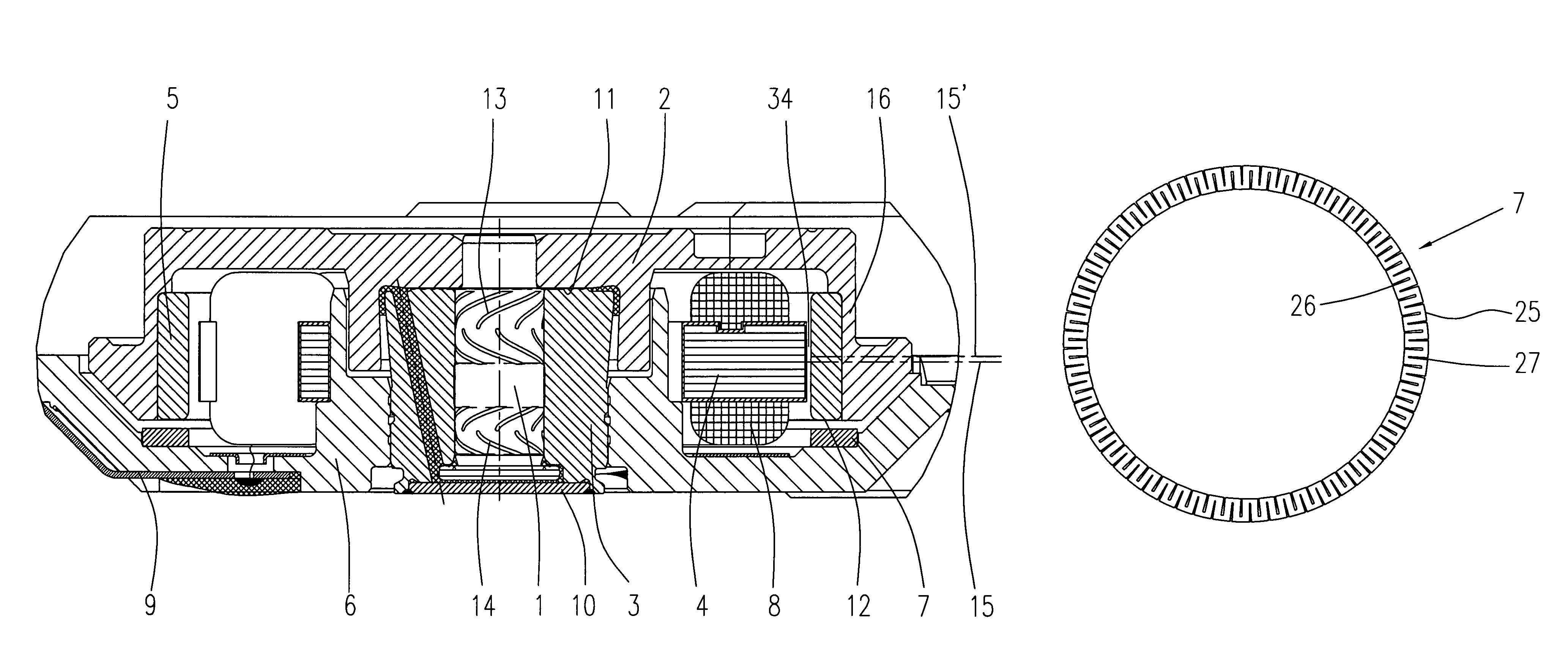
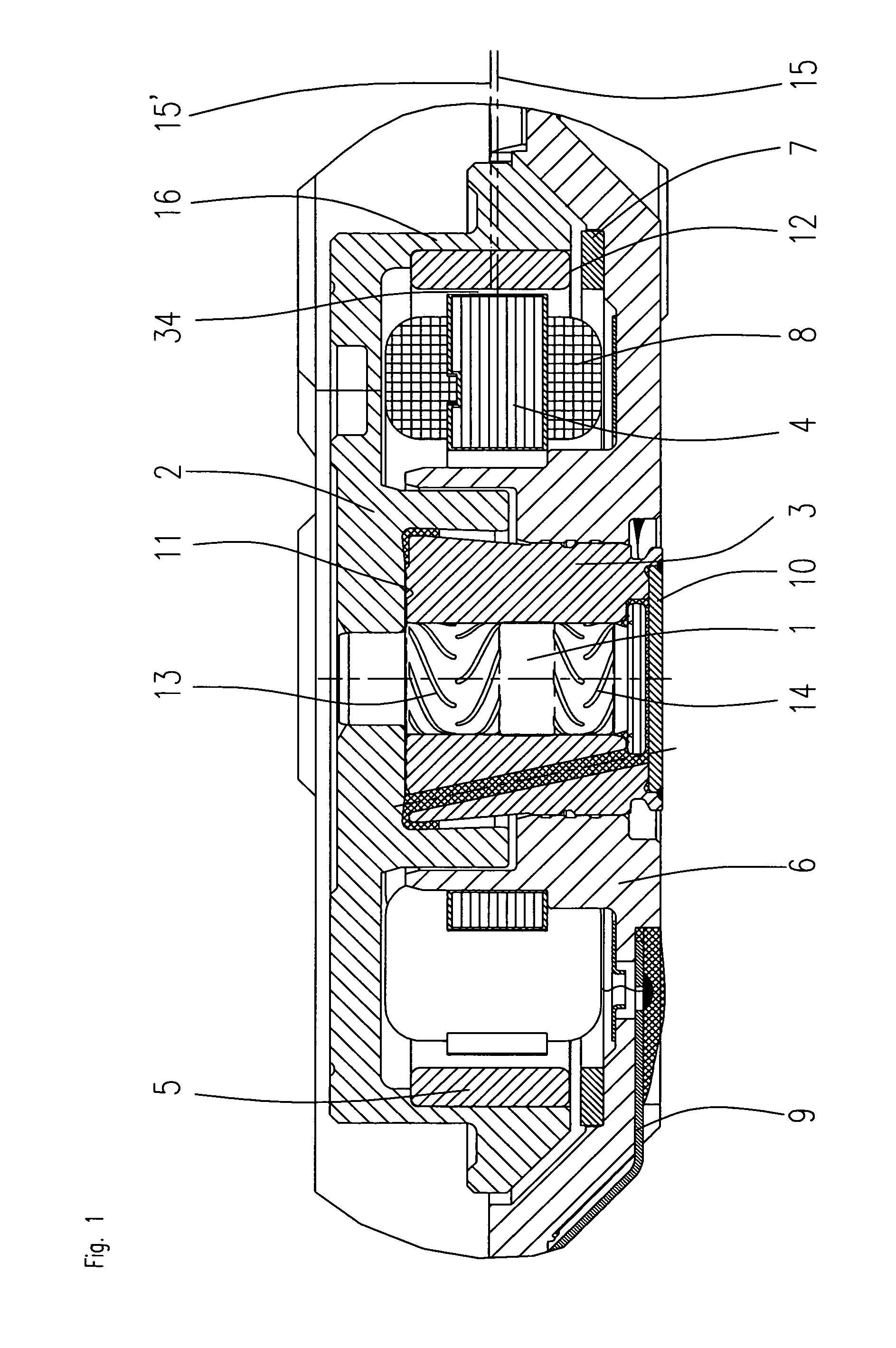
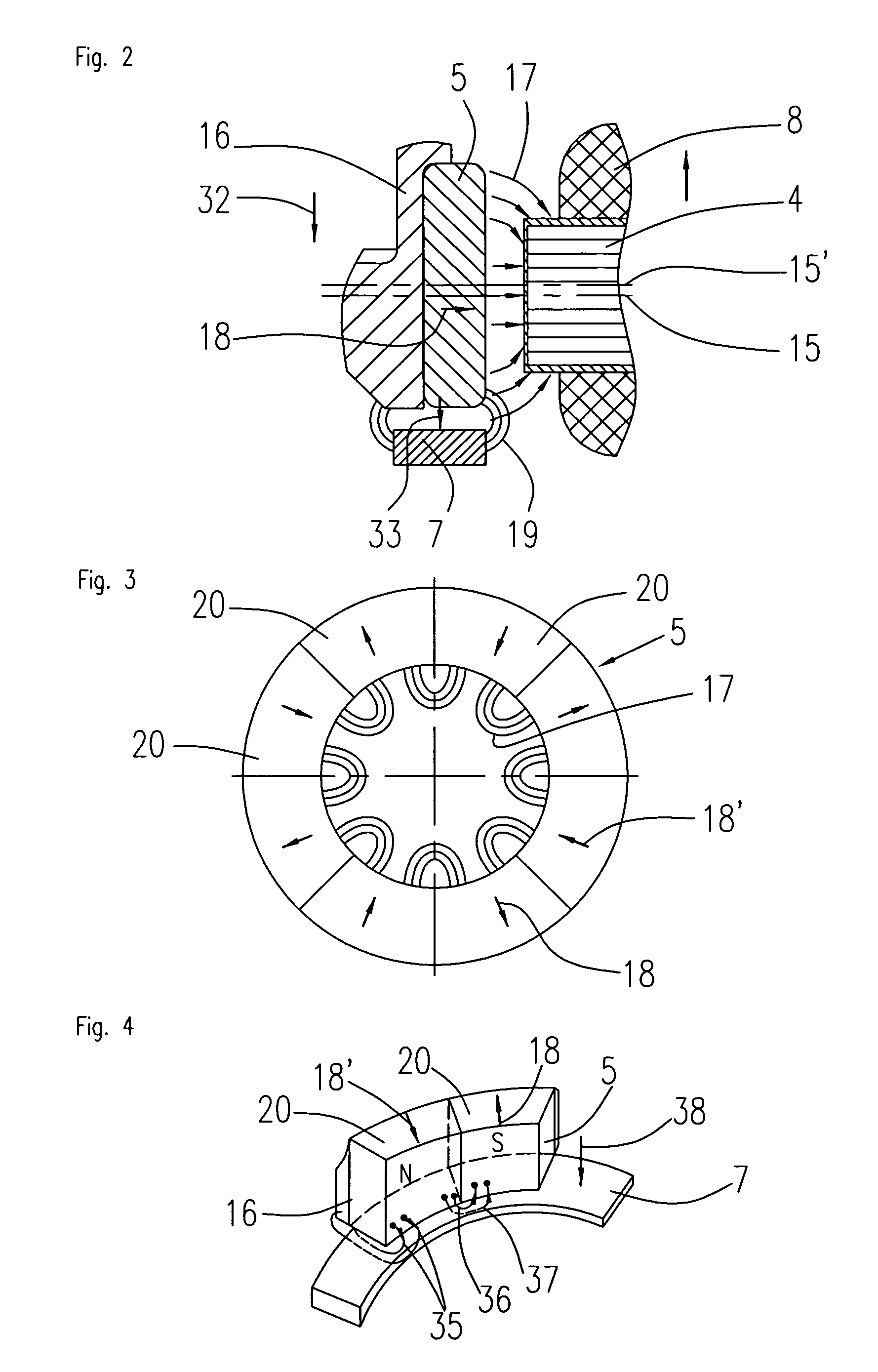
[0062]The permanent magnet motor according to FIG. 1 consists substantially of a shaft 1 that is fixedly connected to a hub 2. At its inside circumference, the hub 2 carries a magnet ring 5 that comprises individual alternately polarized permanent magnets.

[0063]A stator unit 4 is disposed opposite the magnet ring 5 and separated from it by an air gap 34, the stator unit consisting substantially of a laminated sheet metal stack forming a number of stator poles and a winding 8.

[0064]The entire stator unit is fixed in the baseplate 6, the shaft 1 being rotatably supported in a bearing bush 3. An upper fluid bearing is formed in the upper region as an axial bearing 11, and two radial bearings 13, 14 are disposed at a distance from one another. Moreover, a magnetic axial bearing 12 is formed that is made up of the pull ring 7 according to the invention and the permanent magnet ring 5. In addition, a magnetic offset may be formed between the permanent magnet ring 5 and the stator unit 4 w...


PUM


Abstract

A permanent magnetic motor having a magnetic axial bearing and one or more fluid bearings, wherein a stator unit is disposed on a baseplate, the stator unit being disposed opposite a magnet ring made up of permanent magnets and being separated from the magnet ring by an air gap, and the magnet ring is fixed to the inside circumference of a circumferential hub that is supported with respect to a bearing bush by means of the fluid bearings via a shaft, and at least one fluid dynamic axial bearing is preloaded with an axial attractive force component that is at least partly generated by a ferromagnetic pull ring that is fixed to the baseplate and disposed below the magnet ring and permeated by its field lines, characterized in that, seen magnetically, the stator unit is centered with respect to the magnet ring and has no significant axial offset and that the pull ring has no or only relatively low electrical conductivity at high magnetic permeability.

Description

FIELD OF THE INVENTION[0001]The invention relates to a permanent magnetic motor having a magnetic axial bearing according to the preamble of patent claim 1.[0002]A permanent magnet motor of this kind has been made known from a large number of patents submitted by the same applicant. Reference is made to the permanent magnet motors revealed therein. They are to be fully included in the disclosure of the present invention.DESCRIPTION OF RELATED PRIOR ART[0003]It is known for this kind of permanent magnet motor to be used with the bearing combination of a fluid bearing and a magnetic axial bearing. The fluid bearing in turn may consist of a bearing combination of one or more axial bearings with one or more radial bearings.[0004]In constructing a permanent magnet motor having a magnetic offset, the permanent magnets, taking the form of a ring, are disposed with respect to the stator at an axial offset to the magnetic center line of the stator. They are therefore offset axially above or ...

Claims


Application Information

Patent Timeline
Patent Type & Authority Patents(United States)
IPC IPC(8): H02K7/09H02K7/18
CPCH02K7/09F16C25/045F16C17/107F16C2370/12H02K21/22
Inventor BAUER, MARTINPOPOV, VLADIMIR V.BRECHTEFELD, FRANK
Owner MINEBEAMITSUMI INC
Features
  • R&D
  • Intellectual Property
  • Life Sciences
  • Materials
  • Tech Scout
  • Unparalleled Data Quality
  • Higher Quality Content
  • 60% Fewer Hallucinations
Learn More