Apparatus and methods to achieve a variable color pixel border on a negative mode screen with a passive matrix drive

a technology of variable color pixel border and negative mode screen, which is applied in the field of flat panel display screen technology, can solve the problems of inacceptable solution and difficult reading of edge displayed characters by users, and achieve the effect of maximising the use of screen pixels, improving viewability, and simplifying design

Inactive Publication Date: 2010-05-25
QUALCOMM INC
View PDF43 Cites 5 Cited by
  • Summary
  • Abstract
  • Description
  • Claims
  • Application Information

AI Technical Summary

Benefits of technology

[0012]Accordingly, embodiments of the present invention provide an electronic device, e.g., a cell phone, portable computer system, PDA, electronic pager, etc., having a screen that makes maximal use of the available screen pixels while eliminating the problems associated with edge displayed characters in display formats where the pixels of the character are of the same or similar color as the edge region. Embodiments of the present invention are particularly useful in negative mode passive matrix LCD displays that utilize a brighter background and a darker foreground. Embodiments provide the above benefits while being compatible with standard display screen dimensions, formats and driver circuitry. Embodiments of the present invention therefore provide a small display screen with improved viewability, especially at the edge locations. Further, embodiments provide a solution that controls the color of border pixels, yet simplifies the design and lowers the cost of displays by reducing and / or eliminating the dependency of border pixel control on separate timing components. The present invention provides these advantages and others not specifically mentioned above but described in the sections to follow.

Problems solved by technology

This makes reading the edge displayed character very difficult for a user.
However, this solution is not acceptable in the case of a small display screen where every pixel is needed for image and information presentation.

Method used


Image

  • Apparatus and methods to achieve a variable color pixel border on a negative mode screen with a passive matrix drive
  • Apparatus and methods to achieve a variable color pixel border on a negative mode screen with a passive matrix drive
  • Apparatus and methods to achieve a variable color pixel border on a negative mode screen with a passive matrix drive

Examples


Embodiment Construction

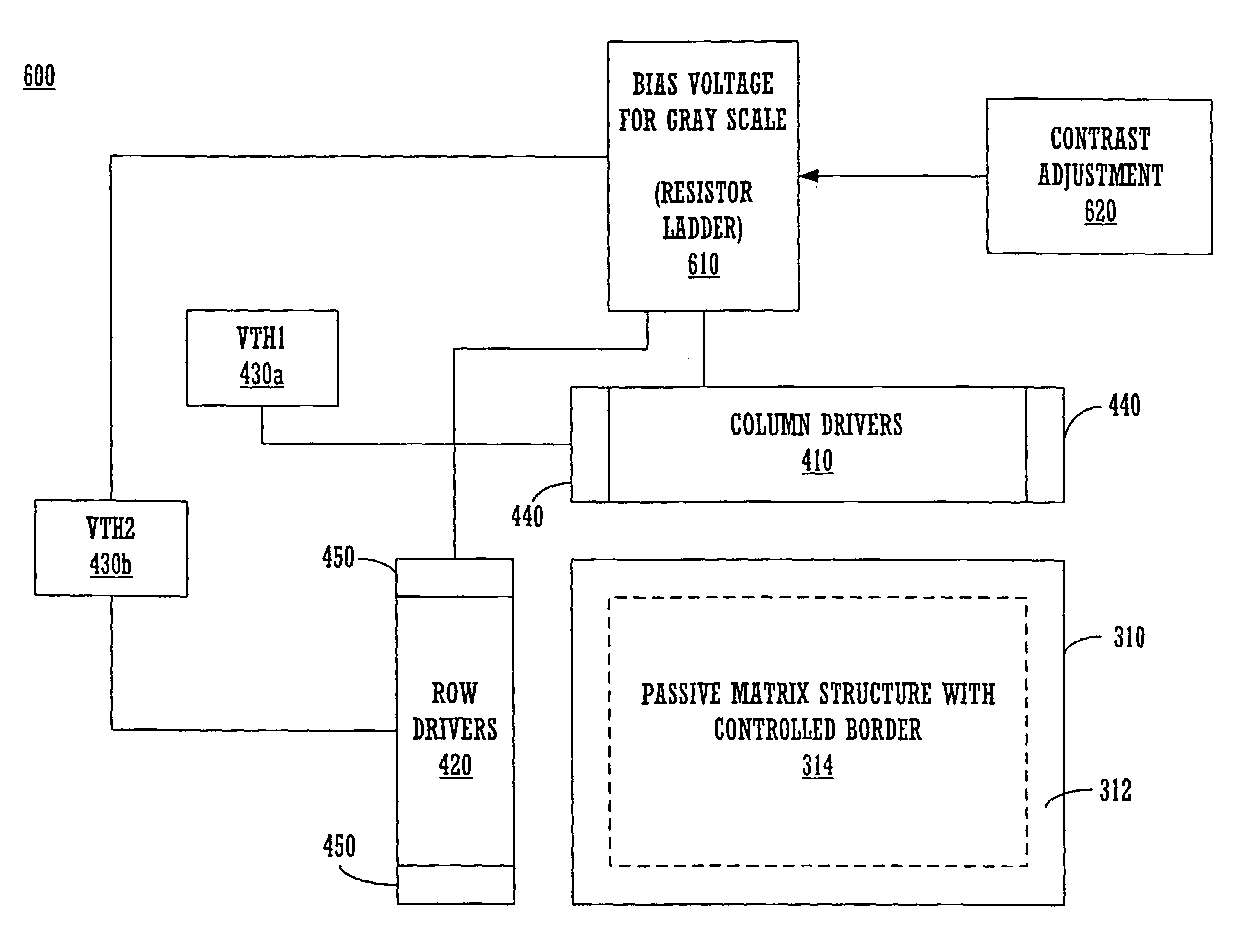
[0047]In the following detailed description of the present invention, a controllable pixel border for a negative display mode passive matrix display screen which provides contrast improvement for increased viewability of edge-displayed characters, numerous specific details are set forth in order to provide a thorough understanding of the present invention. However, it will be recognized by one skilled in the art that the present invention may be practiced without these specific details or with equivalents thereof. In other instances, well known methods, procedures, components, and circuits have not been described in detail as not to unnecessarily obscure aspects of the present invention.

[0048]The following co-pending U.S. application is hereby incorporated by reference, Ser. No. 09 / 818,081, by Shawn Gettemy, Sherridythe Fraser, and David Lum, entitled “Controllable Pixel Border for a Negative Mode Passive Matrix Display Device,” filed Mar. 26, 2001, itself a continuation-in-part of ...


PUM


Abstract

A display unit is constituted by a passive matrix of independently controllable pixels characterized by an active area of n rows and m columns of discrete pixels and a pixel border. The pixel border has a predetermined width, in one embodiment two pixels. The border pixel color state is controlled herein by the frame buffer memory. The pixel border color state is controlled to correspond to information contained in a frame buffer memory locus. This locus may be, in various embodiments herein, a single pixel, a row of pixels, or a number of rows of pixels of frame buffer memory. Each row of pixels may be equal to m and/or n. In one embodiment, the frame buffer controls the border pixels directly via a liquid crystal display controller and drivers, without a timing generation mechanism, such as a timing ASIC.

Description

RELATED APPLICATIONS[0001]This application is related to and claims priority to U.S. patent Ser. No. 10 / 087,369 entitled “Apparatus And Methods To Achieve A Variable Color Pixel Border On A Negative Mode Screen With A Passive Matrix Drive,” by Lum et al., filed on Feb. 28, 2002 now U.S. Pat. No. 6,831,662, which is incorporated herein by reference.[0002]The present application is a continuation-in-part application of co-pending U.S. application Ser. No. 09 / 818,081, by Shawn Gettemy, Sherridythe Fraser, and David Lum, entitled “Controllable Pixel Border for a Negative Mode Passive Matrix Display Device,” filed Mar. 26, 2001 and which is hereby incorporated by reference, and which itself is a continuation-in-part of co-pending U.S. application Ser. No. 09 / 709,142, by Canova, et al., entitled “Pixel Border For Improved Viewability of a Display Device,” filed Nov. 8, 2000 now U.S. Pat. No. 6,961,029 and which is also hereby incorporated by reference. Both incorporated referenced applica...

Claims


Application Information

Patent Timeline
Patent Type & Authority Patents(United States)
IPC IPC(8): G09G5/02
CPCG09G3/3622G09G5/026G09G3/2074G09G5/39G09G5/40G09G2360/12G09G2320/029G09G2320/0606G09G2320/066G09G2340/145G09G2310/0232
Inventor LUM, DAVID W.CHAN, YICHANG
Owner QUALCOMM INC
Why Eureka
Try Eureka