Arrangement for monitoring the location of a mining vehicle in a mine

a technology for mining vehicles and locations, applied in the direction of navigation instruments, position fixation, special data processing applications, etc., can solve the problems of insufficient monitoring accuracy, inexact location determination, and easy occurrence of measurement errors

Active Publication Date: 2010-05-25
SANDVIK MINING & CONSTR OY
View PDF36 Cites 43 Cited by
  • Summary
  • Abstract
  • Description
  • Claims
  • Application Information

AI Technical Summary

Benefits of technology

[0007]The essential idea of the invention is that the mining vehicle comprises means for what is called a dead reckoning. In this case, the mining vehicle is equipped with measuring devices for determining the distance travelled and the direction of the vehicle. During the work cycle, the mining vehicle drives in at least two work areas, i.e. a first and a second work area. The dead reckoning is employed for determining the location in both work areas. Furthermore, at least one identifier whose location is accurately known is arranged in the first work area. When operating in the first work area, the mining vehicle is able to identity the identifier and determines its location based thereon. These location data can be employed for correcting any errors in the dead reckoning. In other words, this allows the location obtained by the dead reckoning to be updated. The control unit of the mining vehicle can use a wireless network or another data transfer connection to transmit the location data to the mine control system, which is thus informed of the exact location of the mining vehicle and is thus able to accurately monitor the operation of the mining vehicle in the mine. Monitoring the location of the mining vehicles operating in a mine allows the tasks performed in the mine to be controlled more efficiently than previously and furthermore it allows the realization of the plans concerning the mine to be monitored.
[0010]The essential idea of an embodiment of the invention is to use a transmitter that transmits a radio-frequency signal as the identifier. The mining vehicle comprises a data transfer unit that is able to receive the signal when the mining vehicle is within the coverage area of the transmitter. The transmitters may be independent units, whereby they do not need to be connected to the mine control system or other networks. Accordingly, arranging individual transmitters in the mine is relatively simple.

Problems solved by technology

In severe mining conditions, measuring error may easily occur, which makes the location determination inexact.
This being so, the location of the mining vehicles operating in the mine cannot be monitored sufficiently accurately.

Method used


Image

  • Arrangement for monitoring the location of a mining vehicle in a mine
  • Arrangement for monitoring the location of a mining vehicle in a mine
  • Arrangement for monitoring the location of a mining vehicle in a mine

Examples


Embodiment Construction

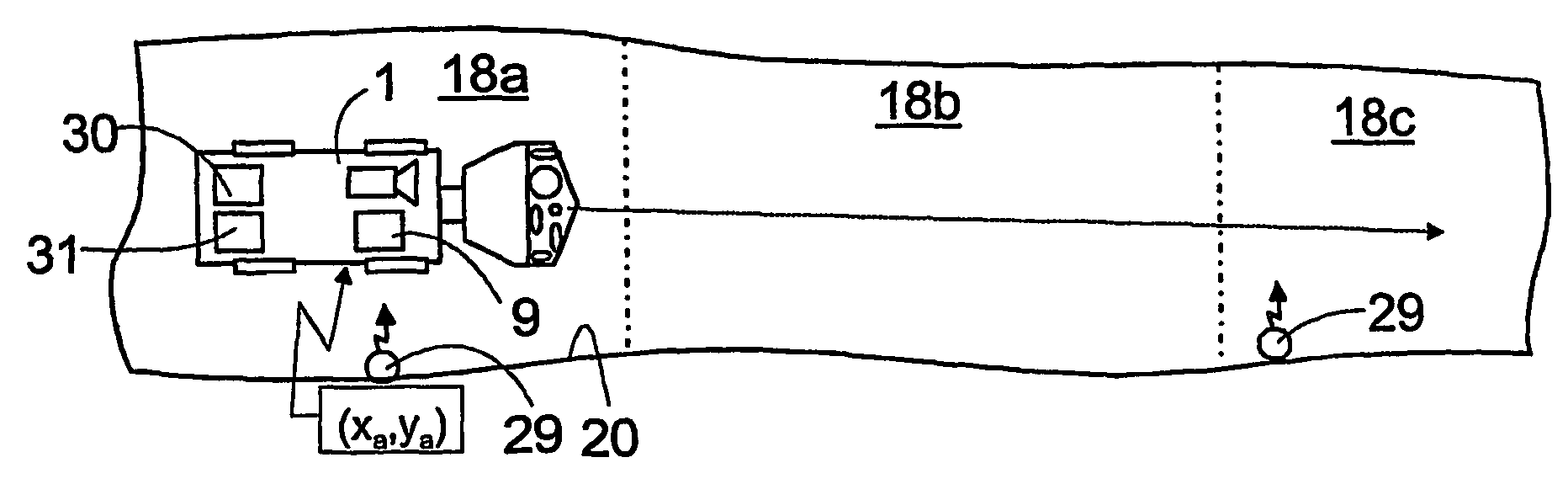
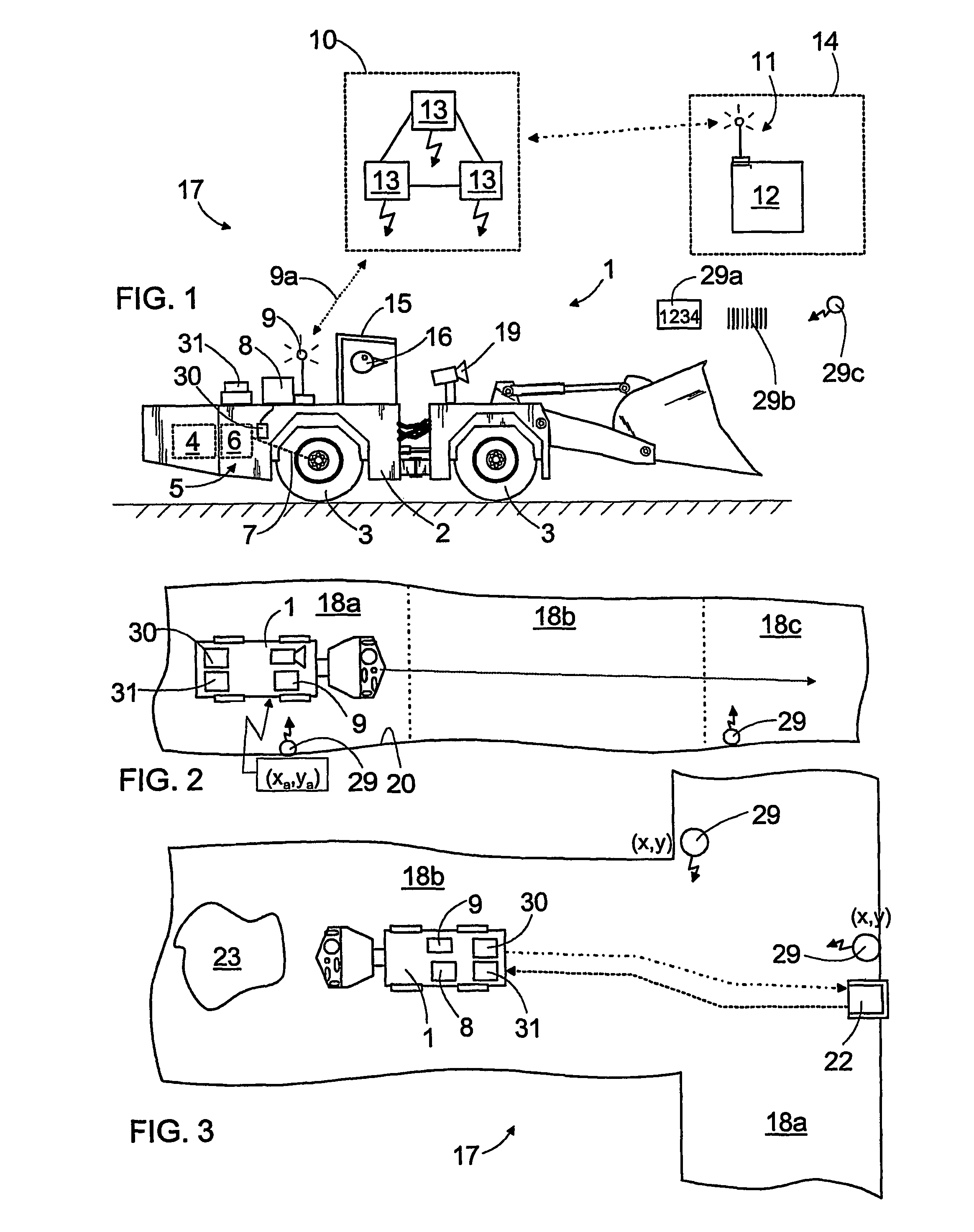
[0024]FIG. 1 shows a mining vehicle 1, in this case a loading vehicle whose front end comprises a bucket for transporting and loading mined material. Alternatively, the mining vehicle 1 may be a rock drilling device or a transport vehicle provided with a platform, for example. The mining vehicle 1 comprises a movable chassis 2 having a plurality of wheels 3, of which at least one is a traction wheel, which an engine 4 employs by means of power transmission 5. The power transmission 5 usually comprises a gearbox 6 and necessary cardan shafts 7, differentials and other transmission means for transferring the rotation torque from the engine 4 to the traction wheels. In addition, the mining vehicle 1 is provided with a control system comprising at least a first control unit 8 arranged to control the actuators in the mining vehicle 1 for steering and using the vehicle. Furthermore, the mining vehicle 1 may comprise a data transfer unit 9 or a terminal by means of which the first control ...


PUM


Abstract

A method and a system for monitoring the location of a mining vehicle in a mine. The mine comprises a first and a second work area. At least one identifier (29) whose exact location is known is arranged in the first work area (18a). The location of the mining vehicle (1) is determined continuously by means of a dead reckoning. The location data, based on the dead reckoning, can be updated by means of the identifier. The location data are transmitted to a mine control system for monitoring the mining vehicle.

Description

BACKGROUND OF THE INVENTION[0001]The invention relates to a method of monitoring the location of a mining vehicle in a mine, the method comprising: driving at least one mining vehicle during one work cycle at least in a first work area and in a second work area of the mine; determining data on the location of the mining vehicle in the mine; transferring said location data to a mine control system; employing, in location data transfer, a data communication connection communicating with the mine control system; and employing the obtained location data in the mine control system for monitoring the operation of the mining vehicle.[0002]The invention further relates to a system for monitoring the location of a mining vehicle in a mine, the system comprising: a first work area and a second work area in the mine, in which areas the mining vehicle is arranged to drive during one work cycle; at least one measuring device for determining the distance travelled by the mining vehicle, and furth...

Claims


Application Information

Patent Timeline
Patent Type & Authority Patents(United States)
IPC IPC(8): G05D3/00G06F19/00G06G7/00G06G7/76G05D1/02E21F13/02G01C21/12G01C23/00G01SG01S1/68G01S5/02
CPCG01C21/12G05D1/0272
Inventor MAKELA, HANNUPULLI, RIKUSOIKKELI, TIMO
Owner SANDVIK MINING & CONSTR OY
Why Eureka
Try Eureka