Integrated combustor-heat exchanger and systems for power generation using the same

a technology of combustor and heat exchanger, which is applied in the direction of machine/engine, engine control, hot gas positive displacement engine plant, etc., can solve the problem of generally not economical removal or recovery of carbon dioxide (cosub>2/sub>) from power generation system, such as from the exhaust of gas turbin

Inactive Publication Date: 2010-06-01
GENERAL ELECTRIC CO
View PDF10 Cites 89 Cited by
  • Summary
  • Abstract
  • Description
  • Claims
  • Application Information

AI Technical Summary

Problems solved by technology

Removal or recovery of the carbon dioxide (CO2) from power generation systems, such as from the exhaust of a gas turbine, is generally not economical due to low CO2 content and low (ambient) pressure of the exhaust.
Therefore, unfortunately, the exhaust containing the CO2 is typically released to the atmosphere, and does not get captured and sequestered into oceans, mines, oil wells, geological saline reservoirs, and so on.

Method used


Image

  • Integrated combustor-heat exchanger and systems for power generation using the same
  • Integrated combustor-heat exchanger and systems for power generation using the same
  • Integrated combustor-heat exchanger and systems for power generation using the same

Examples


Embodiment Construction

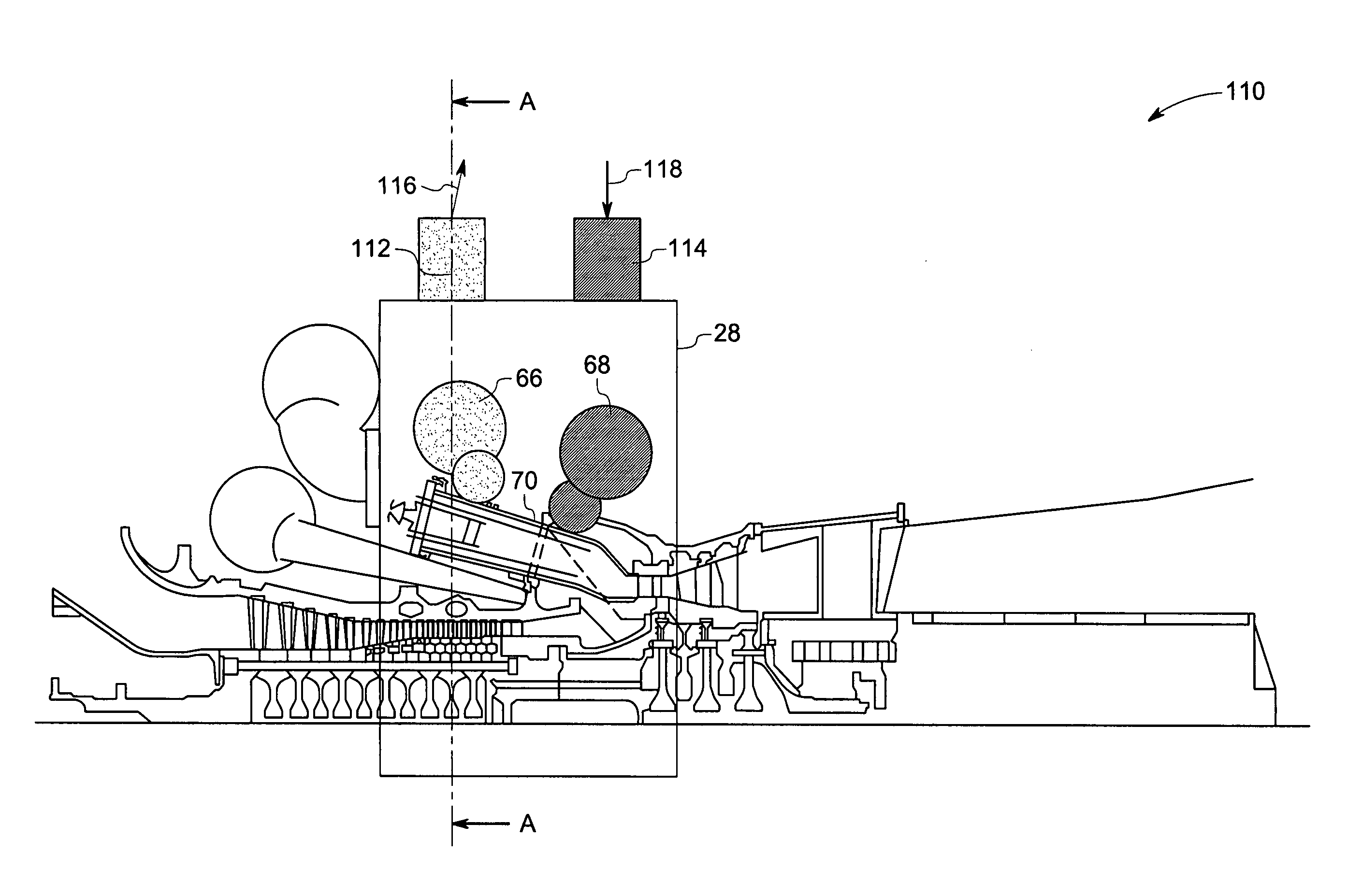
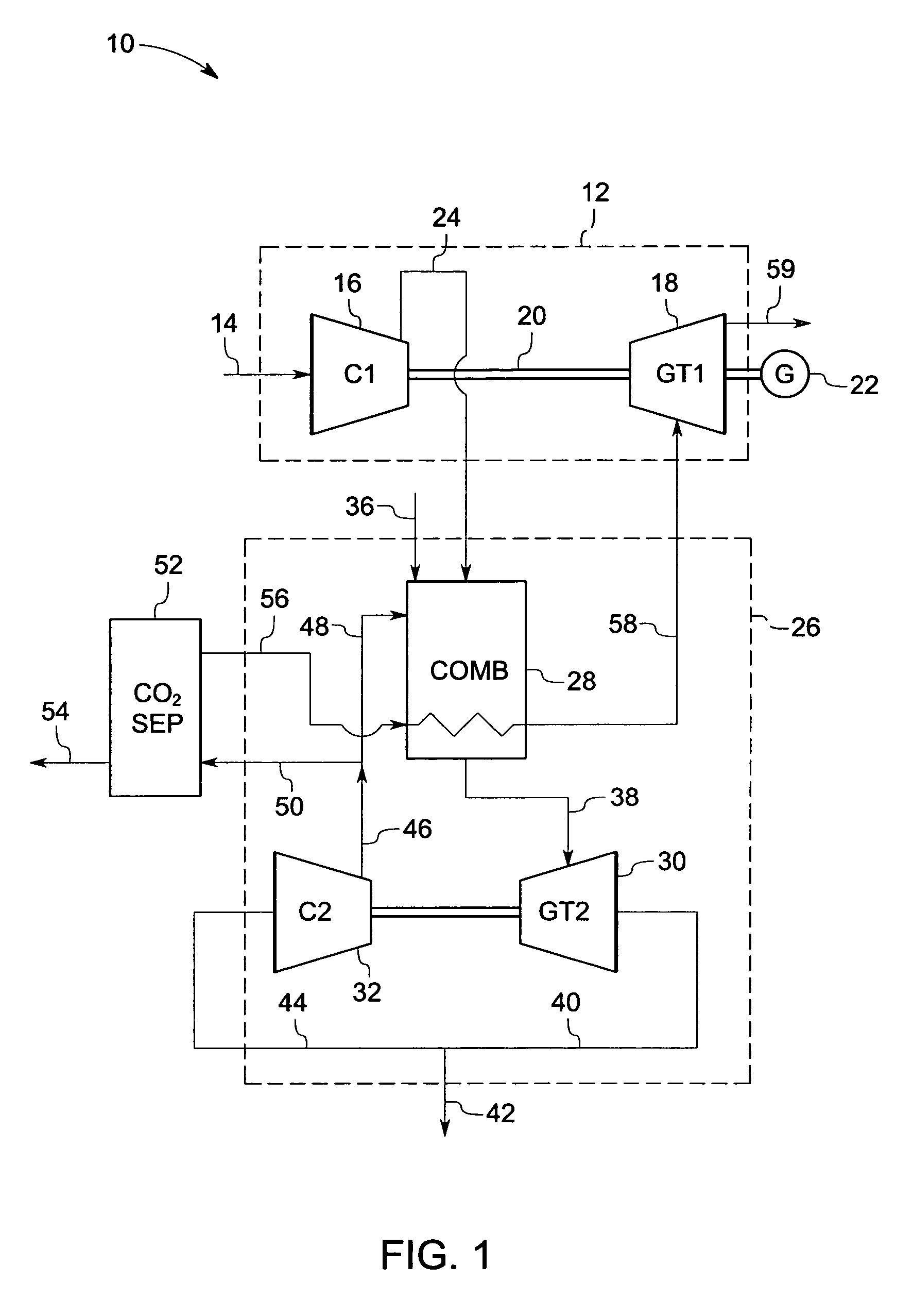
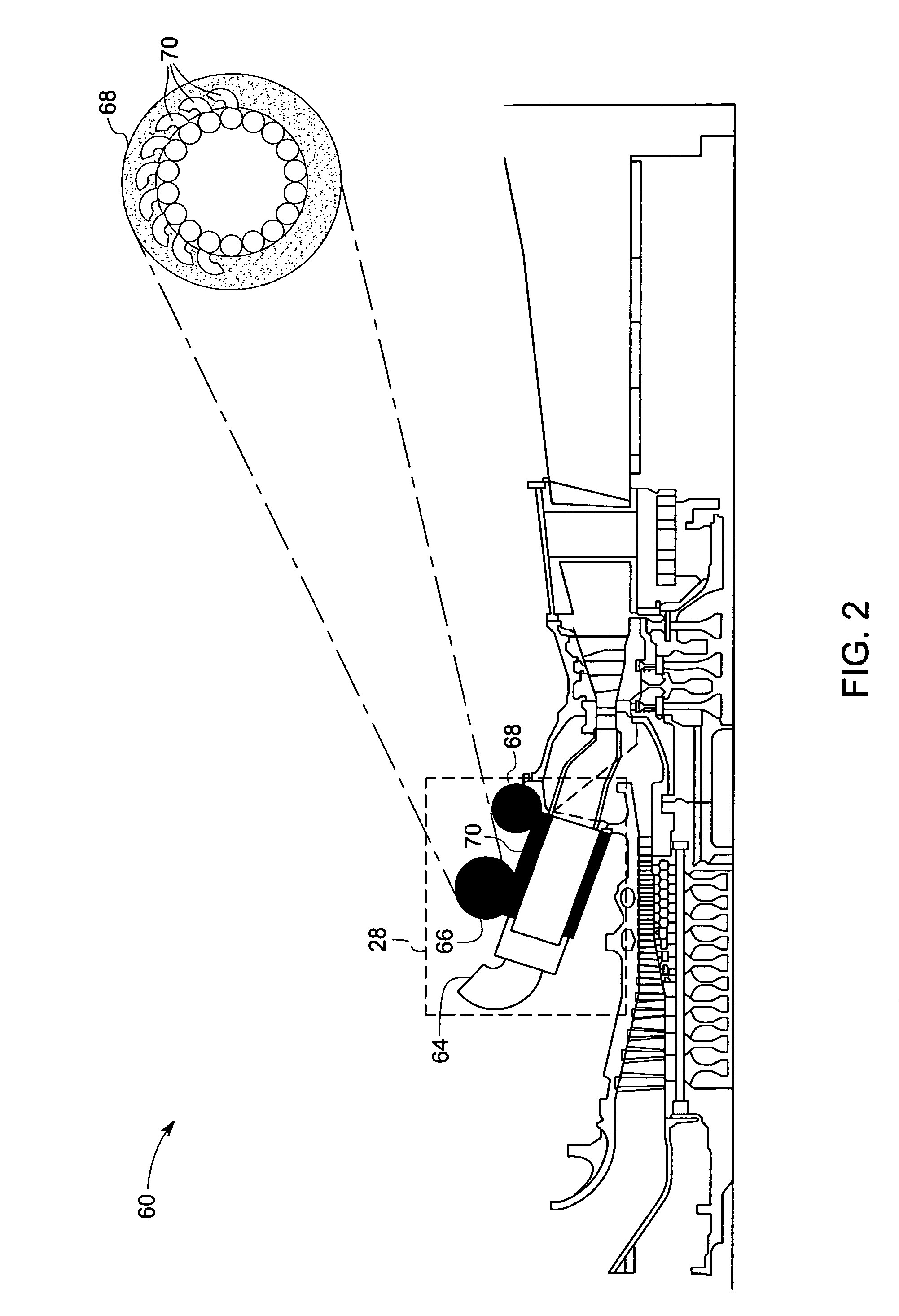
[0020]The present technique provides for two or more exemplary gas turbine systems operating in a power generation system to share a common supply of compressed oxidant. As a result, compression capacity may be freed in one or more of the turbine systems to be employed in the recovery of carbon dioxide (CO2) generated by one or more of the turbine systems. In one example, a compressor in a first turbine system supplies oxidant (via conduits) to a combustion chamber in the first turbine system and also to a combustion chamber in a second turbine system, freeing a compressor in the second turbine system. As discussed below, this freed compression capacity may be employed in the separation and recovery of carbon dioxide (CO2) and other components from the exhaust of one or more of the gas turbines. The recovered CO2 may be sold as product or consumed on-site as feed in other processes, for example. Further, such recovery of CO2 may reduce the amount of CO2 emitted to the environment fr...


PUM


Abstract

A combustor-heat exchanger system comprising a plurality of cans. Each can includes an inner cylinder and an outer cylinder forming an annular space in between, wherein the inner cylinder is configured to receive and combust a fuel and compressed oxidant to generate heat and a hot gas. The outer cylinder is configured to receive a portion of a gas lean in carbon dioxide from a turbine system and utilize the heat from the inner cylinder to generate a heated gas. The combustor-heat exchanger further includes an inlet volute along the surface of the inner cylinder configured to receive the portion of the gas lean in carbon dioxide and distribute the gas lean in carbon dioxide into an axial flow through the annular space of each can. The combustor-heat exchanger also includes an outlet volute along the surface of the outer cylinder configured to receive the heated gas from each can, a first manifold to distribute the gas lean in carbon dioxide stream into each inlet volute and a second manifold to receive the heated gas from each can and generate a hot discharge stream.

Description

BACKGROUND[0001]The invention relates generally to power generation and the efficient recovery of carbon dioxide. More particularly, the invention relates to the integration with carbon dioxide separation with efficient heat recovery and oxygen consumption.[0002]Power generation systems that combust fuels containing carbon, for example fossil fuels, produce carbon dioxide (CO2) as a byproduct as carbon is converted to CO2 during the combustion process. Removal or recovery of the carbon dioxide (CO2) from power generation systems, such as from the exhaust of a gas turbine, is generally not economical due to low CO2 content and low (ambient) pressure of the exhaust. Therefore, unfortunately, the exhaust containing the CO2 is typically released to the atmosphere, and does not get captured and sequestered into oceans, mines, oil wells, geological saline reservoirs, and so on.[0003]In any power generation cycle, once the oxidant is compressed for the combustion process, it is desirable t...

Claims


Application Information

Patent Timeline
Patent Type & Authority Patents(United States)
IPC IPC(8): F02C3/00
CPCF02C6/10F05D2270/08
Inventor EVULET, ANDREI TRISTAN
Owner GENERAL ELECTRIC CO
Why Eureka
Try Eureka