
Fixed cutter drill bit

a drill bit and fixed technology, applied in the field of drill bits, can solve problems such as fluid pressure increase and structure failure, and achieve the effect of maintaining or restoring bit stability

Inactive Publication Date: 2010-06-01
OTS INT
View PDF31 Cites 40 Cited by
  • Summary
  • Abstract
  • Description
  • Claims
  • Application Information

AI Technical Summary

Benefits of technology

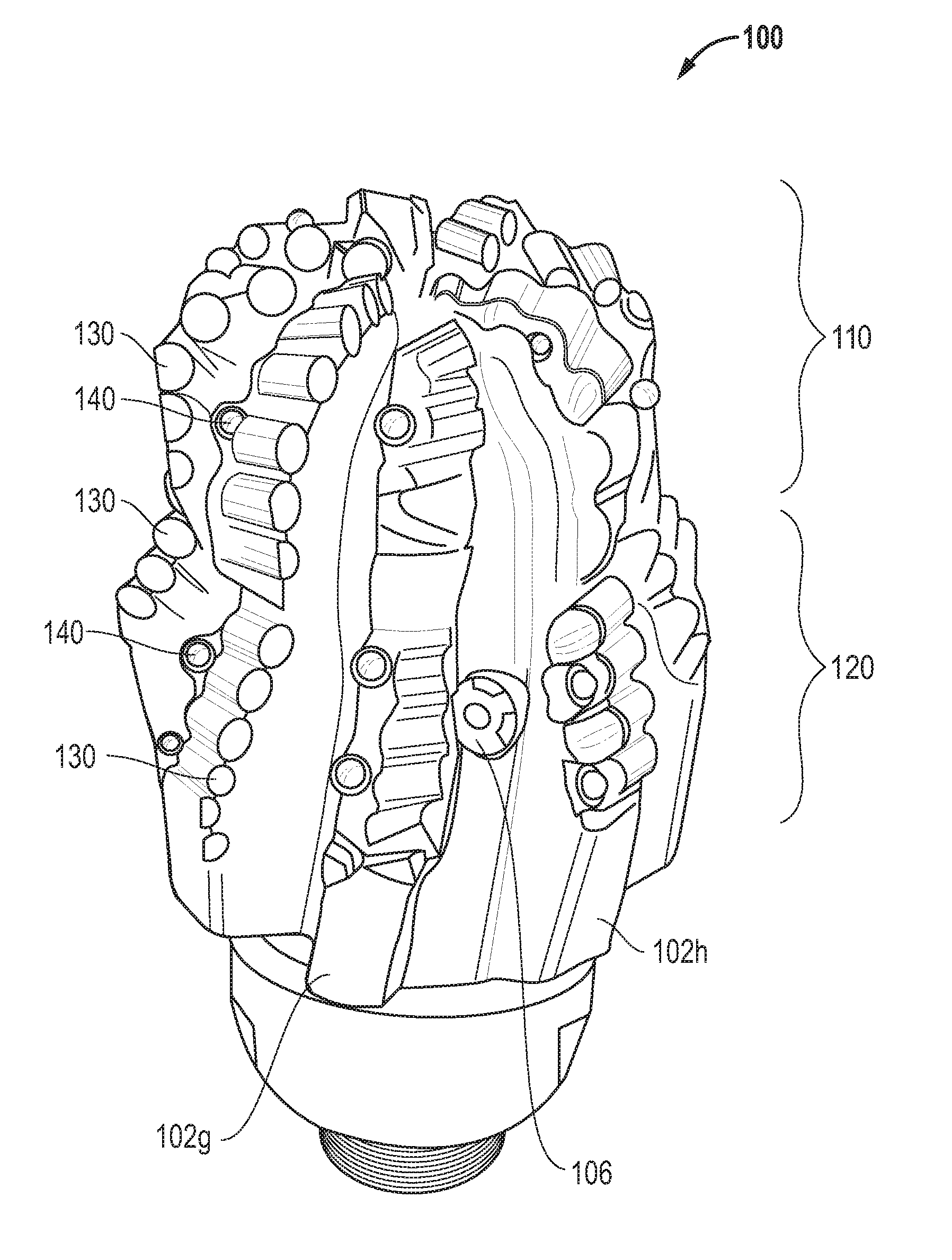
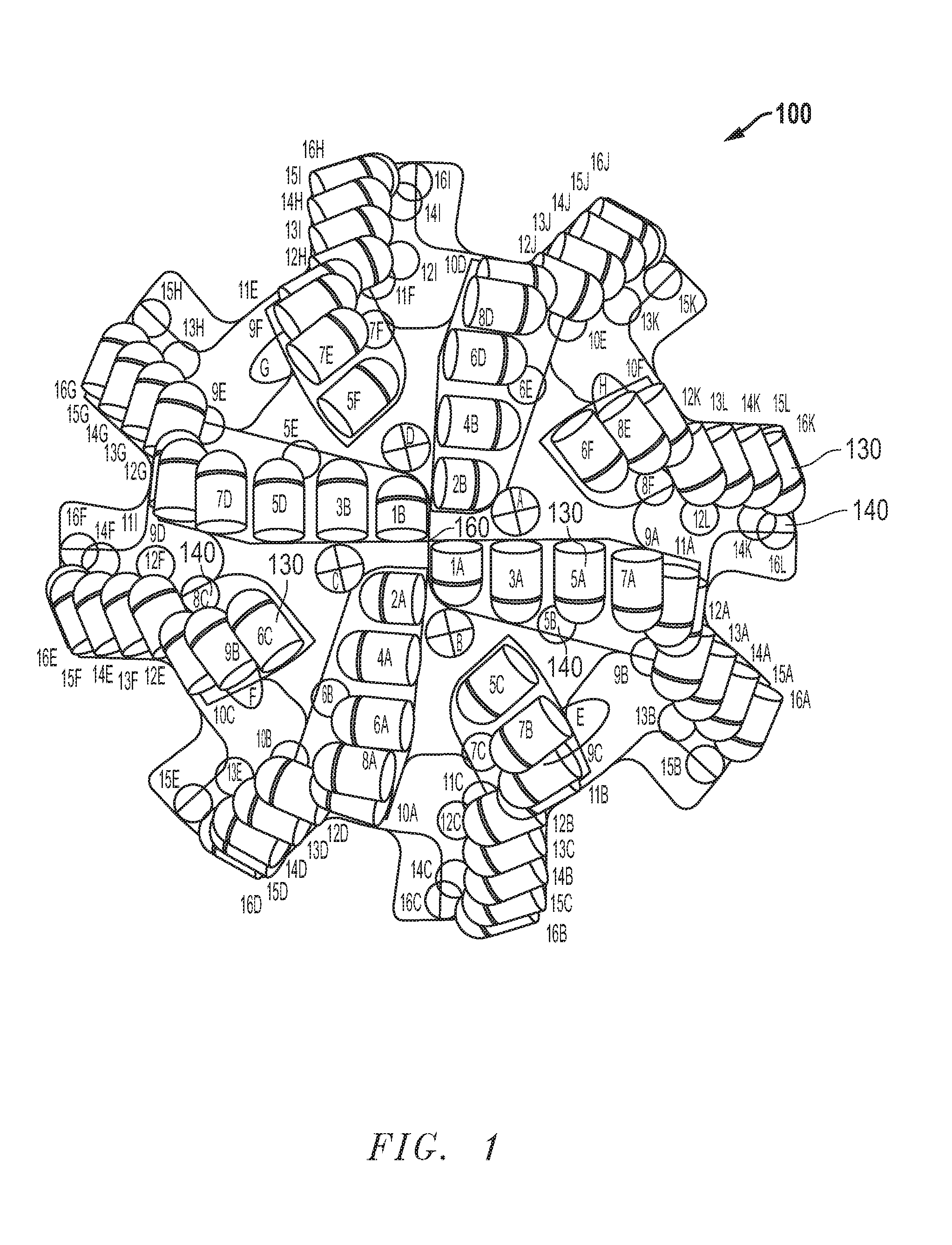
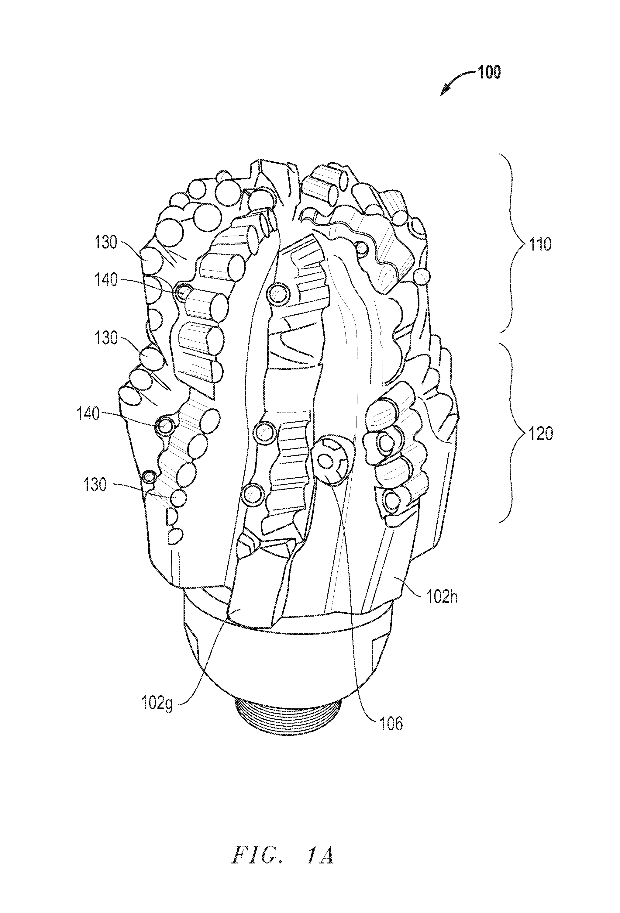
[0010]In the piloting section, cutting structures have been arranged so as to create offsetting cutting forces that result in a net zero imbalance during operation. Furthermore, the piloting section utilizes carefully placed shock studs which aid in protecting the primary cutting structure against over-engagement, axial, or lateral impact (as well as assisting in maintaining or restoring bit stability).

Problems solved by technology

In addition, the location of the fluid supply nozzles on the body of the reamer section serves to indicate catastrophic cutting structure failure below the pilot gage.
This will cause an increase in fluid pressure, indicating the blockage.

Method used


Image

  • Fixed cutter drill bit
  • Fixed cutter drill bit
  • Fixed cutter drill bit

Examples


Embodiment Construction

[0032]This application claims the benefit of U.S. Provisional Patent Application No. 60 / 669,052, filed Apr. 7, 2005 (entitled “A Novel Fixed Cutter Drill Bit”), and applicant incorporates the entirety of that provisional patent application herein by reference.

[0033]The Selection and Design of Effective Drill Bits

[0034]In drilling a borehole in the earth such as for the recovery of oil or for other purposes, many different types of drill bits have been used. The choice of the appropriate type of bit to be used (and the specifics associated with its design) depends upon many factors. One important factor to be taken into consideration is the range of hardnesses that will be encountered during the drilling that takes place through layers of differing formation hardnesses.

[0035]Different types of bits work more or less efficiently against different formation hardnesses. For example, roller cone bits are efficiently and effectively used in drilling through formation materials that are of...


PUM


Abstract

The fixed cutter drill bit disclosed utilizes a unique piloting section and reaming section carefully designed to impart several specific operational advantages. In the piloting section, cutting structures have been arranged so as to create offsetting cutting forces that result in a net zero imbalance during operation. Furthermore, the piloting section utilizes carefully placed shock studs which aid in protecting the primary cutting structure. In addition, the location of the fluid supply nozzles on the body of the reamer section serves to indicate the occurrence of a catastrophic cutting structure failure below the pilot gage.

Description

CROSS-REFERENCE TO RELATED APPLICATIONS[0001]This application claims the benefit of U.S. Provisional Patent Application No. 60 / 669,052, filed Apr. 7, 2005 (entitled “A Novel Fixed Cutter Drill Bit”), and applicant incorporates the entirety of that provisional patent application herein by reference.BACKGROUND OF THE INVENTIONThe Field of the Invention[0002]This invention relates generally to drill bits (and related technologies) of the type used to drill through layers of material, including those comprising rock formations such as those bearing oil and other fossil fuels. As an example, the invention is concerned with fixed cutter drill bits of the type using polycrystalline diamond cutting elements protruding from the face of the bit.[0003]A Challenging Problem: the Selection and Design of Effective Drill Bits[0004]In drilling a borehole in the earth such as for the recovery of oil or for other purposes, many different types of drill bits have been used. The choice of the appropria...

Claims


Application Information

Patent Timeline
IPC IPC(8): E21B12/02E21B10/26
CPCE21B10/26E21B17/1092E21B10/43E21B10/627
Inventor TIPTON, ROBERT GEORGEKEITH, CARL W.STRENK, JR., GERALD A.
Owner OTS INT
Learn More