Ocean wave energy converter (OWEC)

Inactive Publication Date: 2010-06-01
EVANS ANDREW CAAIUS
View PDF20 Cites 18 Cited by
  • Summary
  • Abstract
  • Description
  • Claims
  • Application Information

AI Technical Summary

Benefits of technology

[0010]The ocean wave energy converter or OWEC (the device) described here fulfils all these criteria. It is estimated th

Problems solved by technology

1) The energy of the waves is greatest in open sea far from shore, for example in some areas off the North Atlantic ridge swell heights can average about 8 meters. Closer to shore, wave energy is dissipated due to bottom friction and diffraction effects. Under deep-water conditions installation of wave energy converters can be difficult and expensive. Shore based wave energy converters are easier to install but have lower theoretical capacity and a greater environmental impact.
2) Many wave energy converters use floats that bob up and down on the wave with relation to the seabed, this movement may be used to generate electricity. However these type of energy converters intrinsically only ha

Method used


Image

  • Ocean wave energy converter (OWEC)
  • Ocean wave energy converter (OWEC)
  • Ocean wave energy converter (OWEC)

Examples


Example

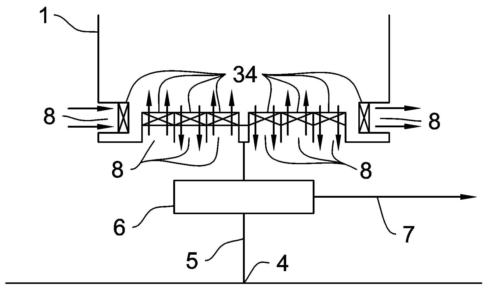
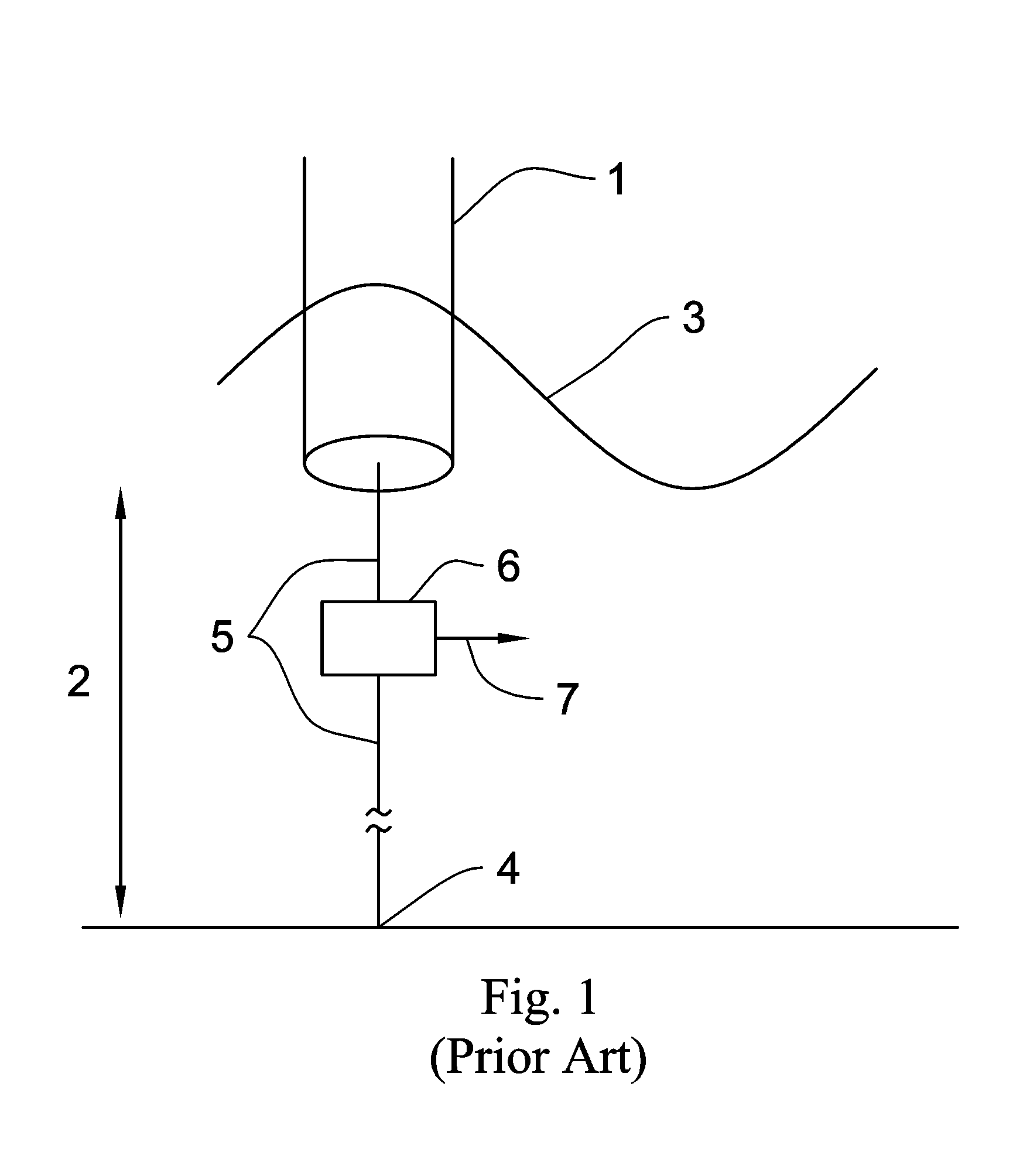
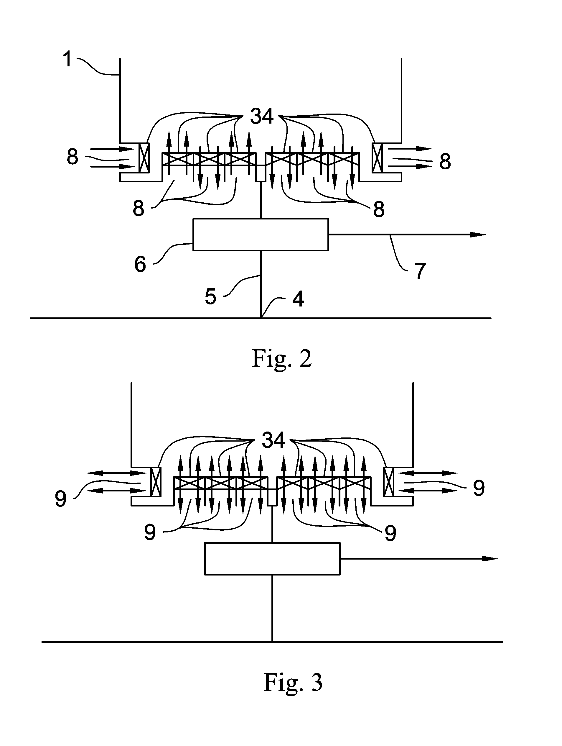
[0023]The OWEC (FIG. 1) essentially consists of a container (1) which in operation is partially submersed to a specific height from the seabed (2) such that the waterline (3) varies in height with the passing of waves. The device is connected to the seabed (4) using cables or supports (5). The device may be erected on a platform supported on the seabed or buoy (6). In FIGS. 2 and 3, the container is fitted with one or a number of pipes (8 or 9) that facilitate the inflow and outflow of seawater between the container's interior and the sea. As waves pass the container it is filled and emptied through these pipes. This is due to a differential created between the water on the inside of the device and the water on the outside of the device due to the device's buoyancy, that it is connected by cables to the seabed or that it is erected on a platform. Different pipes (8) could be used for the inflow and outflow (FIG. 2) or the same pipe (9) could facilitate both the inflow and outflow (F...


PUM


Abstract

A device consisting of a container which is partially submerged in the sea which may be buoyant and connected to the seabed with cables or mounted on a platform and whose interior is connected to its exterior via pipes where in response to the passing of waves is filled and emptied through these pipes. The force of the water flowing through the pipes causes turbines to rotate thus generating electricity which may be transmitted to land. These turbines may be turbines which rotate in different directions depending on the direction of water flow or turbines which maintain the same direction of rotation irrespective of the direction of water flow.

Description

CROSS-REFERENCE TO RELATED APPLICATIONS[0001]This application is an U.S. national phase application under 35 U.S.C. §371 based upon co-pending International Application No. PCT / GB2005 / 003205 filed on Aug. 15, 2005. Additionally, this U.S. national phase application claims the benefit of priority of co-pending International Application No. PCT / GB2005 / 003205 filed on Aug. 15, 2005. The entire disclosures of the prior applications are incorporated herein by reference. The international application was published on Feb. 22, 2007 under Publication No. WO 2007 / 020365 A1.BACKGROUND OF THE INVENTION[0002]1. Field of the Invention[0003]The energy of ocean waves is immense and one of the largest renewable resources of energy that can be harvested by mankind. The US DOE estimate that the total power of waves breaking on the world's coastlines is 2 to 3 billion kW. Ocean wave energy is useful to mankind not only due to its energetic potential but also, unlike wind, is less intermittent as it is...

Claims


Application Information

Patent Timeline
IPC IPC(8): F03B13/00
CPCF03B13/148F03B13/22Y02E10/38Y02E10/30
Inventor EVANS, ANDREW CAAIUS
Owner EVANS ANDREW CAAIUS
Why Eureka
Try Eureka