Pulse width modulator system

a pulse width modulator and pulse width technology, applied in the direction of amplifiers, channel dividing arrangements, synchronous/start-stop systems, etc., can solve the problems of complex and power-consuming compensation to be performed in the pulse width modulator, and the worsening of electromagnetic compatibility and interference (emc/emi) properties

Inactive Publication Date: 2010-06-01
MUSIC GROUP IP
View PDF19 Cites 2 Cited by
  • Summary
  • Abstract
  • Description
  • Claims
  • Application Information

AI Technical Summary

Benefits of technology

[0010]According to the present invention, an advantageous means for modifying a signal to better allow for processing or other kinds of handling by means that do not process all possible signal amplitudes linearly is provided. By means of the present invention, the concentration of signal amplitudes that may be problematic to handle properly by a subsequent means is reduced.
[0117]By substantially preventing certain amplitude ranges to occur within an intermediate output signal without causing harmful alteration of the utility signal an exceptionally useful embodiment has been obtained, allowing a pre-conditioning of a signal to better fit to a processing stage comprising problematic processing within these certain amplitude ranges.

Problems solved by technology

A problem of the disclosed invention is that it requires complex and power consuming compensation to be performed in the pulse width modulator.
A further problem is that the compensation performed causes a worsening of the electromagnetic compatibility and interference (EMC / EMI) properties.

Method used


Image

  • Pulse width modulator system
  • Pulse width modulator system
  • Pulse width modulator system

Examples


Embodiment Construction

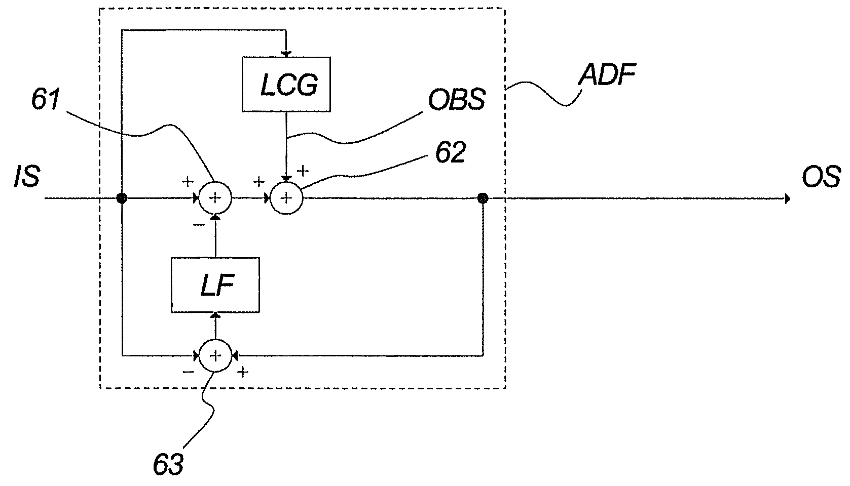
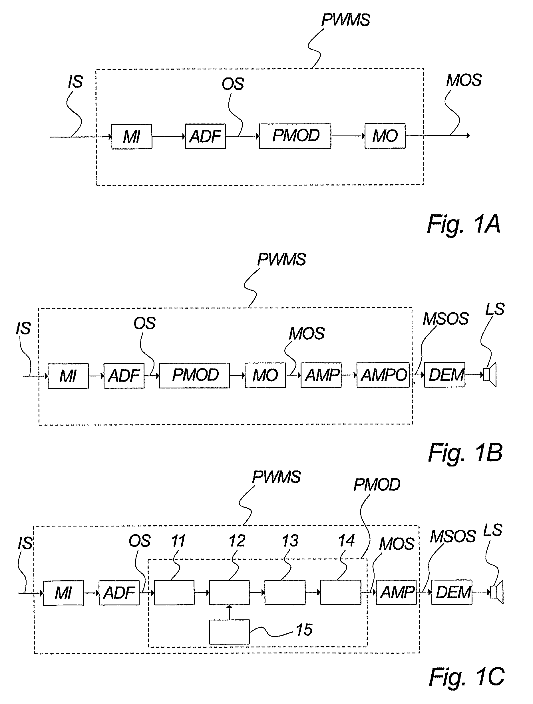
[0178]FIG. 1A illustrates an embodiment of a pulse width modulator system PWMS of the present invention. It comprises a modulator input MI receiving an input signal IS. The input signal may is preferably the utility signal to be pulse width modulated. An amplitude distribution filter ADF of the present invention processes the input signal IS in order to adapt the input signal amplitude distribution to achieve the best performance of subsequent stages. The amplitude distribution filter ADF establishes an output signal OS, also referred to as intermediate output signal, which is fed to a pulse width modulator PMOD. The pulse width modulator PMOD establishes a pulse width modulated representation of the output signal, and outputs it via a modulator output MO as a modulator output signal MOS.

[0179]FIG. 1B illustrates a further embodiment of a pulse width modulator system PWMS of the present invention, and a context for its use. It comprises all elements of FIG. 1A coupled as described a...


PUM


Abstract

The invention relates to pulse width modulator system (PWMS) comprising a modulator system input (MI),a modulator output (MO), an amplitude distribution filter (ADF) ,and a pulse width modulator (PMOD), wherein said amplitude distribution filter (ADF) establishes an intermediate output signal (OS) by modifying the level of the amplitude distribution of an input signal (IS) within at least one predetermined amplitude range of said input signal (IS), said input signal (IS) being received from said modulator system input (MI), and wherein said pulse width modulator (PMOD) provides a modulator output signal (MOS) on said modulator output(MO) on the basis of said intermediate output signal (OS).

Description

FIELD OF THE INVENTION[0001]The present invention relates to a pulse width modulator system comprising an amplitude distribution filter.BACKGROUND OF THE INVENTION[0002]U.S. Pat. No. 5,617,058 discloses a method of minimizing nonlinearities when amplifying pulse width modulated (PWM) signals. A problem of the disclosed invention is that it requires complex and power consuming compensation to be performed in the pulse width modulator. A further problem is that the compensation performed causes a worsening of the electromagnetic compatibility and interference (EMC / EMI) properties.[0003]It is an object of the present invention to provide a pulse width modulator dealing with nonlinearities of, e.g., amplifiers for pulse width modulated signals in a cost-effective way.[0004]It is a further object of the present invention to provide a pulse width modulator with improved electromagnetic compatibility and interference (EMC / EMI) properties.SUMMARY OF THE INVENTION[0005]The invention relates ...

Claims


Application Information

Patent Timeline
Patent Type & Authority Patents(United States)
IPC IPC(8): H03K7/08H03F1/32H03F3/217H04L25/14H04L25/49
CPCH03F1/32H03F3/217H04L25/4902H03F2200/351H03F2200/114
Inventor PEDERSEN, KIM RISHOJARKN.AE BUTTED.S-PEDERSEN, LARS
Owner MUSIC GROUP IP
Why Eureka
Try Eureka