Solid electrolytic capacitor and method of producing the same

a technology of solid electrolytic capacitors and electrolytic capacitors, which is applied in the manufacture of electrolytic capacitors, electrolytic capacitors, coatings, etc., can solve the problems of insufficient reduction of esr and high esr (equivalent series resistance), and achieve excellent storage characteristics, low esr, and low esr.

Active Publication Date: 2010-06-01
SANYO ELECTRIC CO LTD
View PDF15 Cites 16 Cited by
  • Summary
  • Abstract
  • Description
  • Claims
  • Application Information

AI Technical Summary

Benefits of technology

[0007]An object of the present invention is to provide a solid electrolytic capacitor having low ESR (equivalent series resistance) and excellent in storage characteristics and a method of producing the same.

Problems solved by technology

However, in the solid electrolytic capacitor disclosed in JP-A No. 07-153650, since the conductivity of manganese dioxide is low, there occurs a problem that ESR (equivalent series resistance) becomes high.
However, by this technique, ESR could not decrease sufficiently.

Method used


Image

  • Solid electrolytic capacitor and method of producing the same
  • Solid electrolytic capacitor and method of producing the same
  • Solid electrolytic capacitor and method of producing the same

Examples


example 1

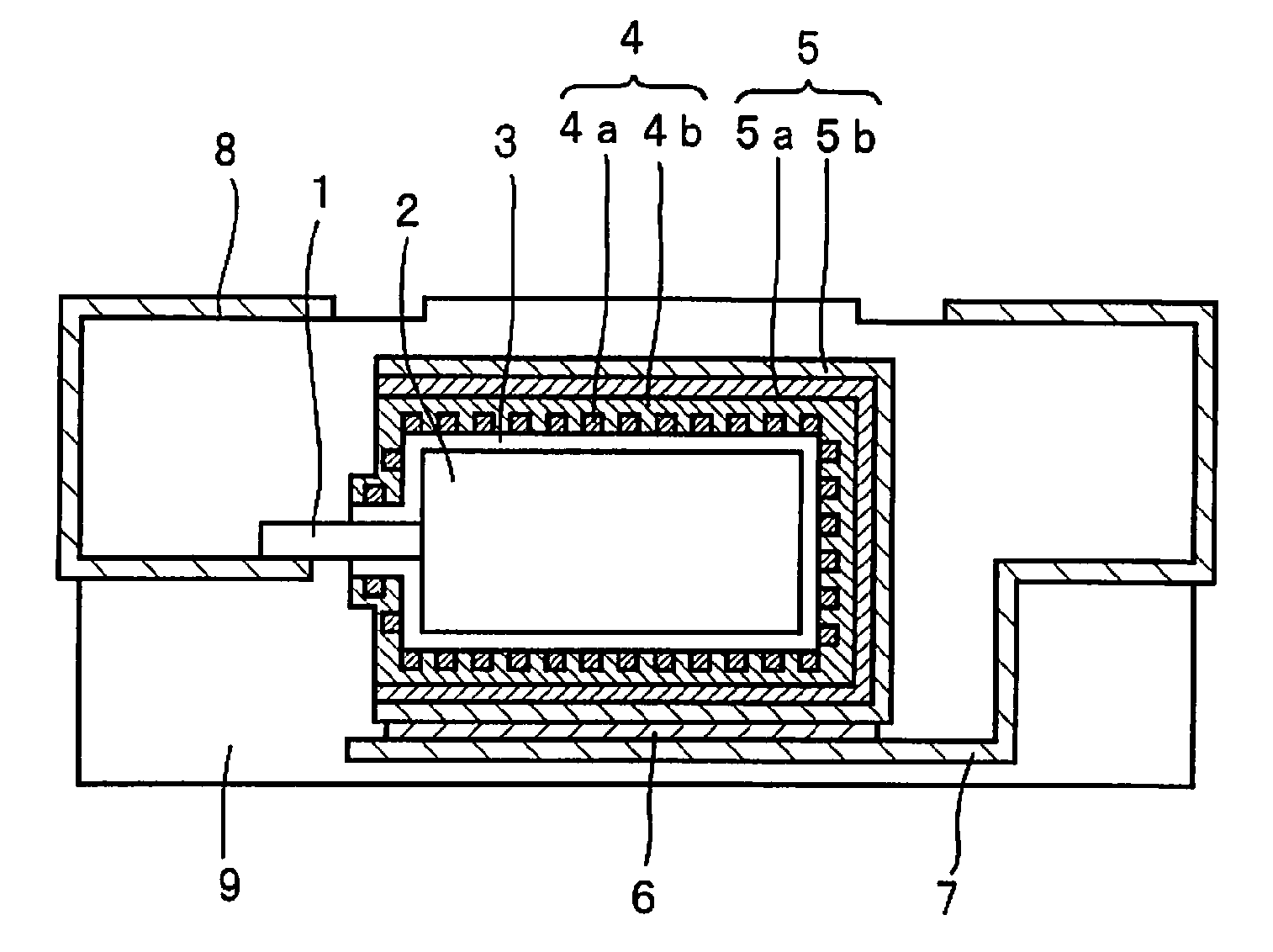
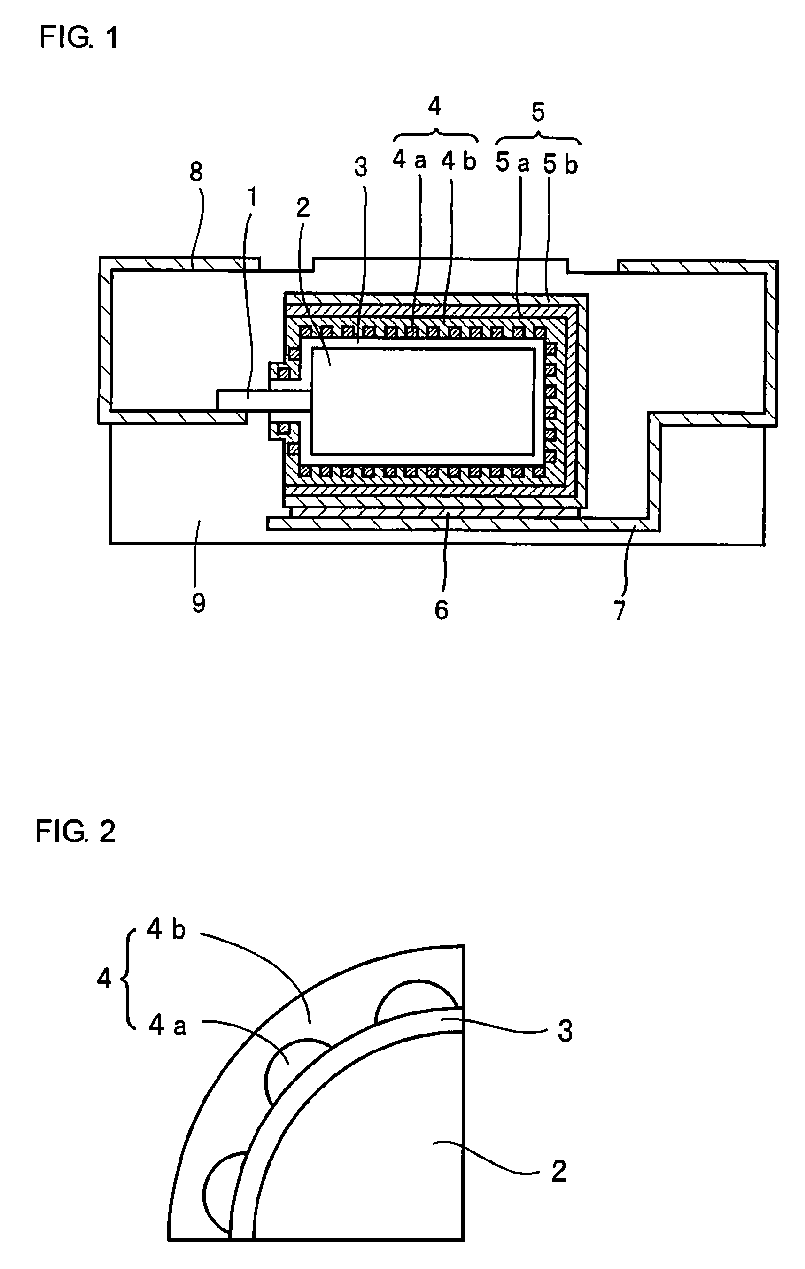
[0038]Step 1: A powder of niobium metal with an average particle diameter of 2 μm was sintered to form an anode 2 made of a porous sintered body in which a metal lead wire 1 of niobium is embedded. The anode 2 was anodized at a constant voltage of 10 V for 10 hours in an aqueous 0.5 wt. % phosphoric acid solution kept at 60° C. to form a dielectric layer 3 containing mainly niobium oxide on the surface of the anode 2.

[0039]Step 2: A capacitor element in which the dielectric layer 3 was formed was immersed in an aqueous oxidizing agent solution containing 20 wt. % of ferric p-toluenesulfonate for 5 minutes to react with vapor of ethylenedioxy thiophene monomer for 10 minutes and thereafter, heat treatment was carried out at 130° C. for 20 minutes to form a conductive polymer layer 4a of polyethylenedioxy thiophene like islands on the surface of the dielectric layer 3. Next, the anode 2 in which the conductive polymer layer 4a was formed is immersed in an aqueous 30 wt. % manganese ni...

example 2

[0043]In this Example, a solid electrolytic capacitor was produced in the same manner as in Example 1, except that the conductive polymer layer 4a was formed using polypyrrole. Practically, after the dielectric layer 3 was formed in the step 1 of Example 1, it was immersed in an aqueous oxidizing solution containing 20 wt. % of ferric p-toluenesulfonate for 5 minutes to react with vapor of pyrrole monomer for 10 minutes to form a conductive polymer layer 4a of polypyrrole like islands on the surface of the dielectric layer 3. Besides that, the solid electrolytic capacitor was produced in the same manner as in Example 1.

examples 3 to 9

[0060]Herein, the relations of the coating ratio of the conductive polymer layer with ESR and storage characteristics were investigated.

[0061]Solid electrolytic capacitors of Examples 3 to 9 were produced in the same manner as in Example 1, except that immersion in an oxidizer containing 20 wt. % of ferric p-toluenesulfonate was carried out and reaction time (polymerization duration) with vapor of ethylenedioxy thiophene pyrrole monomer was changed to be 1 minute, 2 minutes, 5 minutes, 10 minutes, 15 minutes, 40 minutes, 90 minutes, and 120 minutes in the step 2 in Example 1.

[0062]As be described above, ESR and the capacity retention ratio in storage characteristics were measured. The measurement results are shown in Table 2.

[0063]

TABLE 2Polymerization TimeCoating RatioThickness ofCapacityfor Conductiveof ConductiveManganeseRetention RatioPolymer LayerPolymer LayerDioxide Layerin Storage(min.)(%)(nm)ESRCharacteristicsEx. 31230200105Ex. 42330125100Ex. 551030110105Ex. 1102030100100Ex....


PUM

PropertyMeasurementUnit
thicknessaaaaaaaaaa
conductivityaaaaaaaaaa

Abstract

The present invention relates to a solid electrolytic capacitor provided with a anode made of a metal or an alloy having valve action, a dielectric layer formed on the anode, and an electrolyte layer consisting of a conductive polymer layer formed so as to have contact with a portion of the region on the dielectric layer surface and a manganese dioxide layer formed so as to have contact with the other portion of the region on the dielectric layer surface.

Description

BACKGROUND OF THE INVENTION[0001]1. Field of the Invention[0002]The present invention relates to a solid electrolytic capacitor and a method of production the same.[0003]2. Description of the Related Art[0004]Since niobium has a dielectric constant about 1.8 times as high as that of tantalum, which is a material for conventional solid electrolytic capacitors, it draws attention as a material for next generation, high capacity solid electrolytic capacitors. Japanese Patent Application Laid-Open (JP-A) No. 07-153650 discloses a solid capacitor obtained by successively forming a solid electrolyte of manganese dioxide and a conductive layer for a cathode on an anode sintered body obtained by sintering a metal powder for valve action such as tantalum and niobium.[0005]However, in the solid electrolytic capacitor disclosed in JP-A No. 07-153650, since the conductivity of manganese dioxide is low, there occurs a problem that ESR (equivalent series resistance) becomes high.[0006]JP-A No. 5-...

Claims


Application Information

Patent Timeline
Patent Type & Authority Patents(United States)
IPC IPC(8): H01G9/02
CPCH01G9/0036H01G9/025H01G11/56H01G11/82H01G11/48H01G9/028H01G9/032Y10T29/417Y02E60/13
Inventor KATO, KIKUKOYANO, MUTSUMITAKATANI, KAZUHIRONISHIMURA, KOICHIUMEMOTO, TAKASHINONOUE, HIROSHI
Owner SANYO ELECTRIC CO LTD
Why Eureka
Try Eureka