

Solid electrolytic capacitor and fabrication method thereof
a technology of electrolytic capacitors and solid electrolytic capacitors, which is applied in the manufacture of electrolytic capacitors, electrolytic capacitors, coatings, etc., can solve the problems of increasing leakage current, and achieve the effect of low esr, high capacitance and low leakage curren
- Summary
- Abstract
- Description
- Claims
- Application Information
AI Technical Summary
Benefits of technology
Problems solved by technology
Method used
Image

Examples
example 2
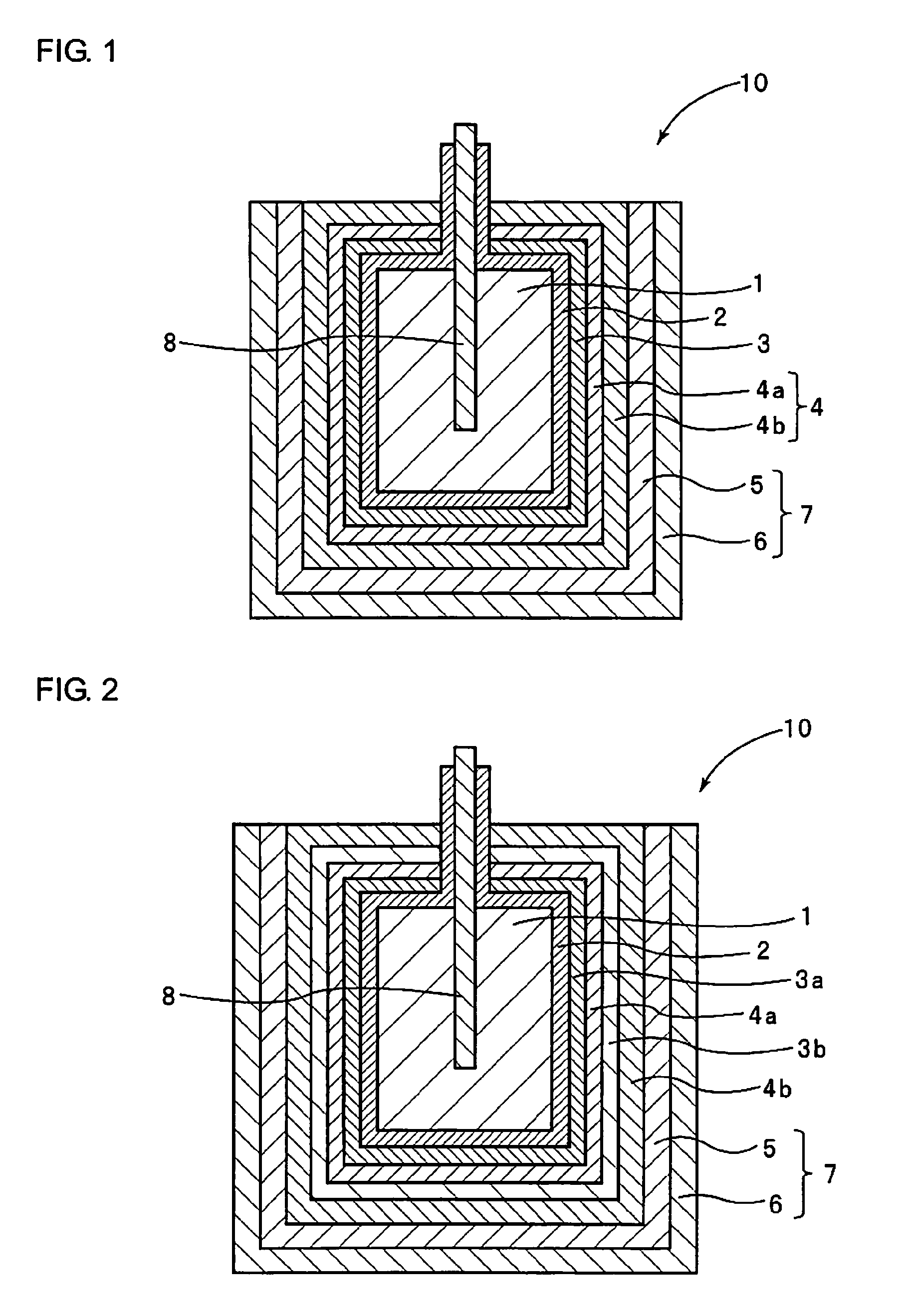
[0063]FIG. 2 is a schematic sectional view which shows a solid electrolytic capacitor of this Example. As shown in FIG. 2, in the solid electrolytic capacitor of this Example, the dielectric layer 2 is formed on the anode 1 and then the first coupling agent layer 3a is formed in the same manner as in Example 1. Subsequent to formation of the first coupling agent layer 3a, the first conductive polymer layer 4a is formed.
[0064]Subsequent to formation of the first conductive polymer layer 4a, the anode was immersed in a 25° C. isopropyl alcohol solution containing 0.5 mM of octadodecylphosphonic acid for 1 hour, washed with isopropyl alcohol and then dried at 60° C. for 10 minutes, as similar to Example 1. As a result, the second coupling agent layer 3b was deposited on the dielectric layer.
[0065]Subsequent to deposition of the second coupling agent layer 3b, the second conductive polymer layer 4b was formed in the same manner as in Example 1.
[0066]Subsequent to formation of the second...
example 4
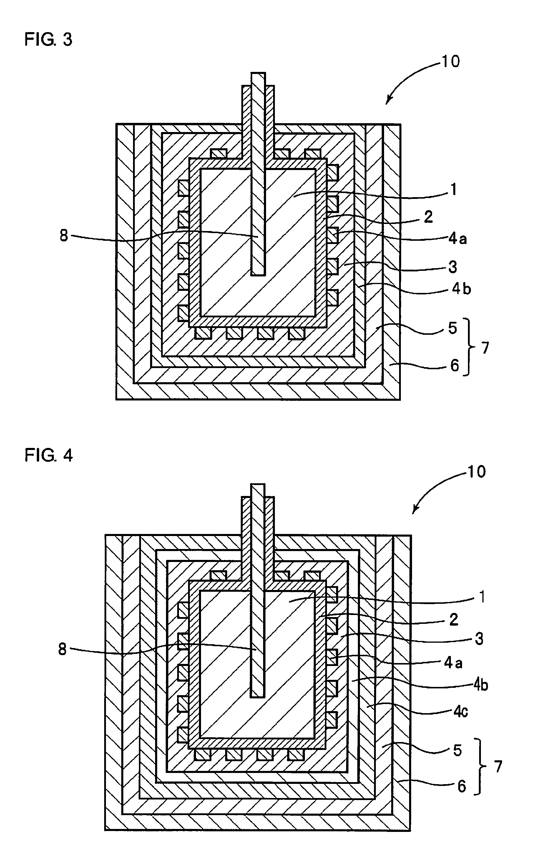
[0085]FIG. 4 is a schematic sectional view which shows a solid electrolytic capacitor of this Example.
[0086]In this Example, the first conductive polymer layer 4a is formed on discrete surface portions of the dielectric layer 2, as shown in FIG. 4. Subsequent to formation of the first conductive polymer layer 4a, the coupling agent layer 3, the second conductive polymer layer 4b and the third conductive polymer layer 4c are successively formed.
[0087]Subsequent to formation of the dielectric layer 2 on the anode 1, the first conductive polymer layer 4a was formed in the same manner as in Example 1. However, the anode was immersed in the ethanol solution containing pyrrole for 1 minute and then in the aqueous solution containing ammonium persulfate and alkylnaphthalenesulfonic acid for 1 minute, so that the first conductive polymer layer 4a was formed as a pattern of islands distributed over the dielectric layer 2.
[0088]Subsequently, the coupling agent layer 3 was deposited over the f...
example 5
[0092]FIG. 5 is a schematic sectional view which shows a solid electrolytic capacitor of this Example.
[0093]In this Example, the first conductive polymer layer 4a is formed on discrete surface portions of the dielectric layer 2, as shown in FIG. 5. Subsequent to formation of the first conductive polymer layer 4a, the first coupling agent layer 3a, the second conductive polymer layer 4b, the second coupling agent layer 3b and the third conductive polymer layer 4c are successively formed.
[0094]Subsequent to formation of the dielectric layer 2 on the anode 1, the first conductive polymer layer 4a was formed as a pattern of islands in the same manner as in Example 4. The first coupling agent layer 3a was subsequently formed on the first conductive polymer layer 4a in the same manner as in Example 4. The coupling agent layer 3a was deposited to overlie the first conductive polymer layer 4a as well as the surface regions of the dielectric layer that remained uncovered by the first conduct...
PUM
| Property | Measurement | Unit |
|---|---|---|
| constant voltage | aaaaa | aaaaa |
| thickness | aaaaa | aaaaa |
| current | aaaaa | aaaaa |
Abstract
Description
Claims
Application Information