RLC window size reconfiguration

a radio link control and window size technology, applied in the field of wireless telecommunications, can solve the problems of large amount of ue memory being unused for most ues, unable to allocate memory for the first ps rab, and reducing performan

Active Publication Date: 2010-06-01
OPTIS WIRELESS TECH LLC
View PDF6 Cites 63 Cited by
  • Summary
  • Abstract
  • Description
  • Claims
  • Application Information

AI Technical Summary

Problems solved by technology

But without the ability to reconfigure RLC window size, such ample memory allocation for the first PS RAB cannot occur.
Naturally, this results in reduced performance, particularly before the second PS RAB is setup (which may never occur).
Since two parallel PS RABs may only be used in a fraction of the PS connections, this implies that a large amount of the UE memory is unused for most UEs and the throughput for PS connections unnecessarily low.
Moreover, when the window size is decreased the UE actions are not unambiguous and potentially very problematic.

Method used


Image

  • RLC window size reconfiguration
  • RLC window size reconfiguration
  • RLC window size reconfiguration

Examples


first example embodiment

/ Mode for UE

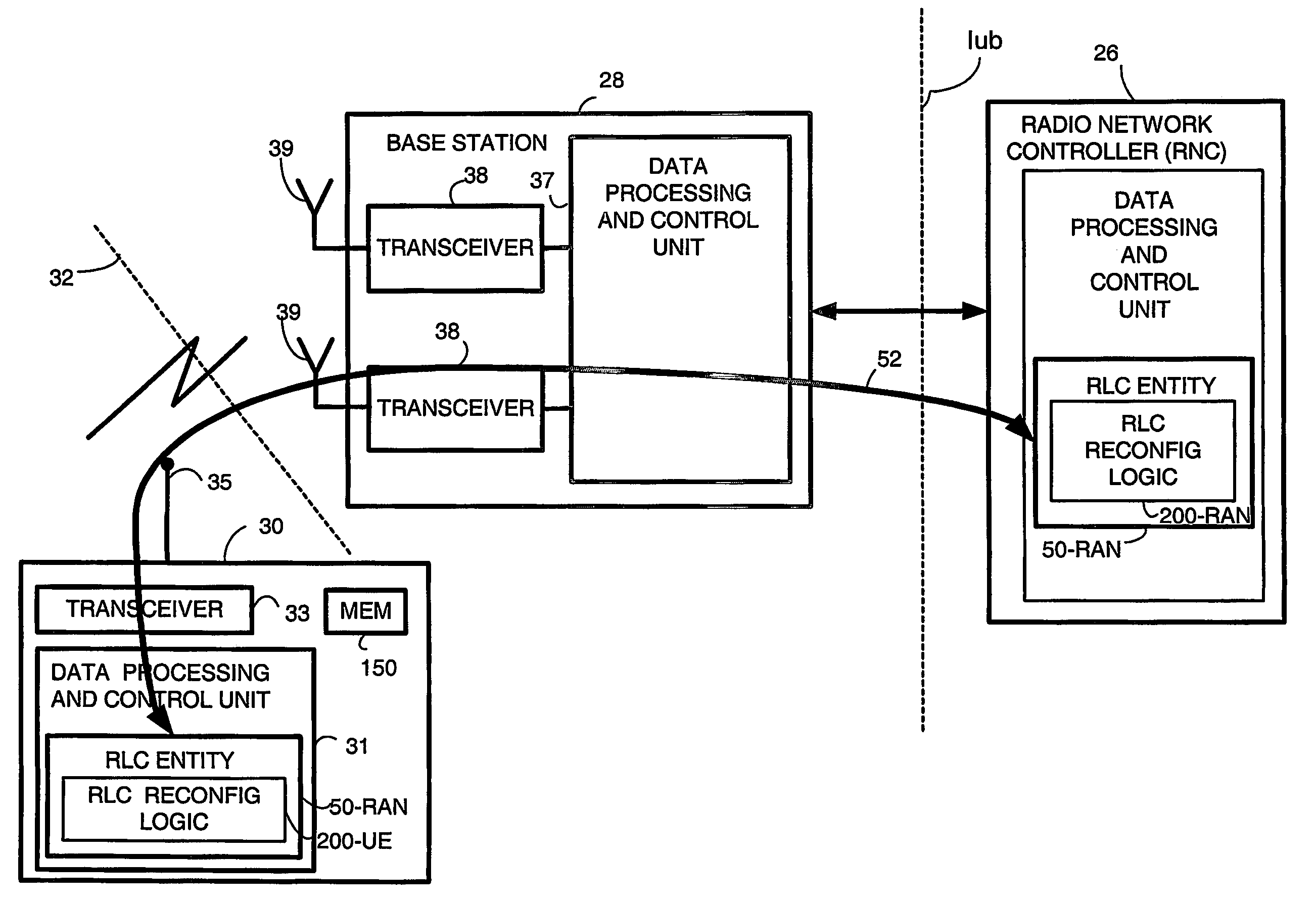
[0066]In a first example embodiment and mode of operation, the radio link control (RLC) entity 50-UE through its RLC reconfiguration logic 200-UE: (A) discards any downlink RLC protocol data units (PDUs) which were received as being within the old receiver buffer window but which are outside the new receiver buffer window; and (B) retains in the radio link control (RLC) buffer memory any uplink RLC protocol data units (PDUs) whose receipt by the radio access network has not been positively acknowledged.

[0067]Rationale for the first embodiment / mode is based on considerations of effects in reducing the window both on the receiver side and the transmitter side. Concerning reduction of the receiver window, when the receiver window is reduced, some of the PDUs received in the old receiver window may end up being outside the new receiver window. In order to free memory in the first embodiment these PDUs are discarded in the UE and treated as not being received. This implies th...

second example embodiment

/ Mode for UE

[0081]In some regards a second example embodiment and mode of operation is more sophisticated than the first embodiment / mode. In the second example embodiment and mode of operation, the radio link control (RLC) entity through its RLC reconfiguration logic 200-UE: (A) retains all downlink RLC protocol data units (PDUs) stored in the receiver buffer, even if outside the new receiver buffer window until the receiver buffer window can be advanced; and (B) retains all uplink RLC protocol data units (PDUs) stored in the transmitter buffer even if outside the new transmitter buffer window.

[0082]In view of the foregoing, FIG. 7 illustrates selected, basic, representative actions performed by a RLC entity 50, and RLC reconfiguration logic 200-UE in particular, in accordance with the second embodiment and second mode during a RLC reconfiguration operation. In similar manner as with the preceding RLC reconfiguration operation of FIG. 6, as action 7-1 the UE RLC entity 50-UE checks ...


PUM


Abstract

A telecommunications device comprises a transceiver (33); a radio link control entity (50); and, a radio link control (RLC) buffer memory (150). The transceiver (33) which enables the device to communicate over an air interface (32). The radio link control entity (50) forms uplink RLC protocol data units (PDUs) for transmission over the air interface (32) and receives downlink RLC protocol data units (PDUs) over the air interface (32). The radio link control (RLC) buffer memory (150) is configured to include a transmitter buffer for storing the uplink RLC protocol data units (PDUs) and a receiver buffer for storing the downlink RLC protocol data units (PDUs). The radio link control entity includes RLC reconfiguration logic means (200) which reconfigures at least one of a size of a transmitter buffer window and a size of a receiver buffer window. In performing the reconfiguration, the RLC reconfiguration logic means implements a strategy for handling at least one of (1) downlink RLC protocol data units (PDUs) which are outside a new receiver buffer window; and (2) uplink RLC protocol data units (PDUs) which are either outside a new transmitter window or whose receipt by the radio access network has not been positively acknowledged.

Description

BACKGROUND[0001]1. Field of the Invention[0002]The present invention pertains to wireless telecommunications, and particularly to method and apparatus for reconfiguration of radio link control (RLC) parameters during a connection.[0003]2. Related Art and Other Considerations[0004]In a typical cellular radio system, wireless user equipment units (UEs) communicate via a radio access network (RAN) to one or more core networks. The user equipment units (UEs) can be mobile stations such as mobile telephones (“cellular” telephones) and laptops with mobile termination, and thus can be, for example, portable, pocket, hand-held, computer-included, or car-mounted mobile devices which communicate voice and / or data with radio access network. Alternatively, the wireless user equipment units can be fixed wireless devices, e.g., fixed cellular devices / terminals which are part of a wireless local loop or the like.[0005]The radio access network (RAN) covers a geographical area which is divided into ...

Claims


Application Information

Patent Timeline
Patent Type & Authority Patents(United States)
IPC IPC(8): H04M1/00H04L1/16H04L1/18H04L12/56H04W28/04
CPCH04L1/1832H04L1/187H04L1/16H04W28/04H04L1/1874H04L1/1835H04L1/18H04L47/27H04L65/40
Inventor BERGSTROM, JOAKIMVAN LIESHOUT, GERT-JANTORSNER, JOHAN
Owner OPTIS WIRELESS TECH LLC
Why Eureka
Try Eureka