Window well assembly

a technology for windows and wells, applied in door/window applications, walls, foundation engineering, etc., can solve the problems of difficulty in separating individual window wells, deformation or damage of window wells, and requiring substantial space, and achieve the effect of convenient assembly and low manufacturing cos

Active Publication Date: 2010-06-08
WESTLAKE ROYAL BUILDING PROD INC
View PDF12 Cites 9 Cited by
  • Summary
  • Abstract
  • Description
  • Claims
  • Application Information

AI Technical Summary

Benefits of technology

[0005]The spacer coupling is preferably carried between common, adjacent, flanges of the first and second well units. Each coupling has an elongated protrusion projecting outward from an outward surface of the flange and spaced outward from an outward face of the retaining wall. When the assembly is in the stored state, a bore of the coupling in each flange of the well unit receives a distal end of the protrusion projecting from the adjacent well unit thus mating the coupling. This mating of the distal end in the bore prevents distortion of the well units when in the stored state. Preferably, each coupling also has a web spanning between the outward face of the retaining wall and the protrusion. A distal stop edge of the web is spaced sufficiently from the outward surface of the contiguous flange so that when the assembly is in the stored state, an inward surface of a flange of the next adjacent unit is in contact with the distal stop edge. This spacing created by the stop edge prevents the units from sticking together when in the stored state.
[0007]Objects, features and advantages of the present invention include a window well assembly having a plurality of well units that can be stacked or nestled in a compact arrangement for packaging, storage and shipping without becoming stuck together or deformed. Other advantages include a relatively lightweight assembly that is versatile, robust, inexpensive to manufacture, and easy to assemble.

Problems solved by technology

Such window wells are typically quite large, and therefore require substantial space for storage, transportation, and the like.
Although nesting of window wells to decrease the space requirements is typically attempted, various problems have been encountered.
For example, the window wells may bind together when nested, thereby creating difficulty when separating the individual window wells for installation and the like.
Furthermore, if a large number of window wells are nested, and / or an external force is applied, the window wells may become deformed or damaged.

Method used


Image

  • Window well assembly
  • Window well assembly
  • Window well assembly

Examples


Embodiment Construction

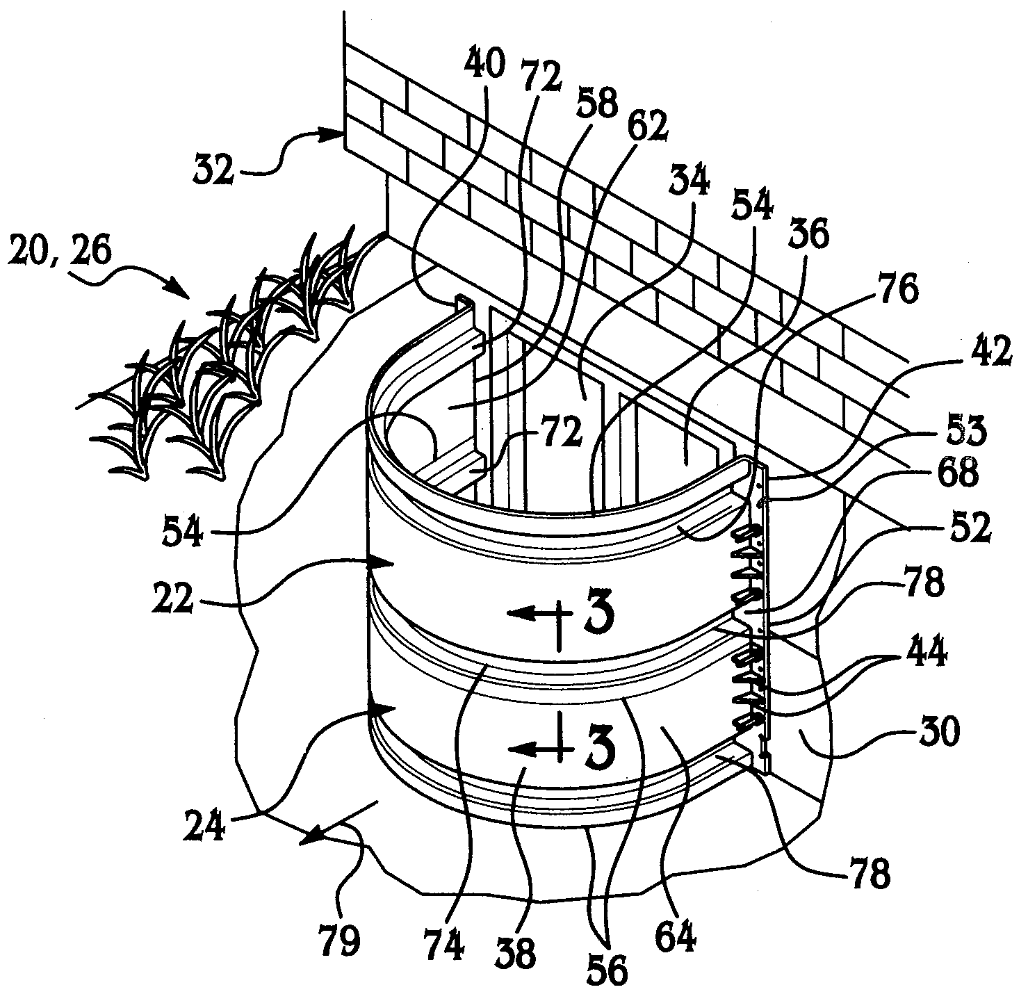
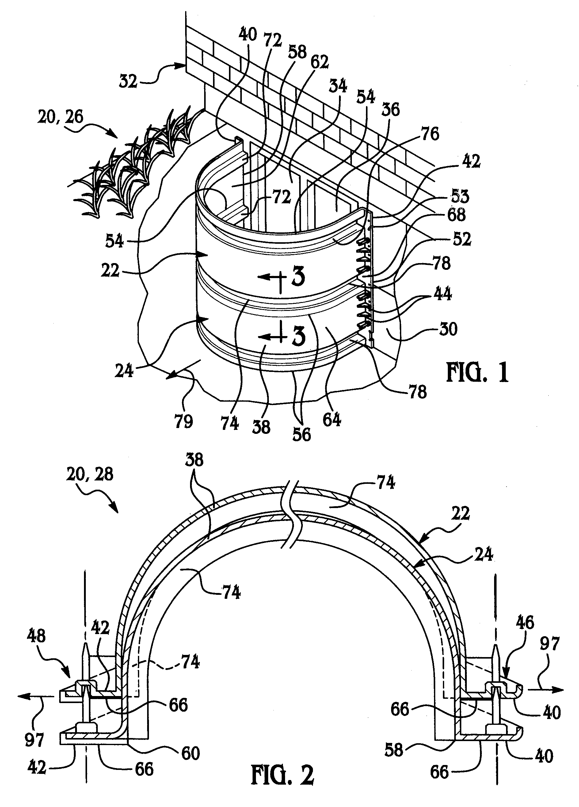
[0019]Referring to FIGS. 1 and 2, a window well assembly 20 embodying the present invention preferably has at least a first well unit 22 and a second well unit 24 illustrated in an assembled state 26 and a stored state 28. When in the assembled state 26, any one of the well units 22, 24 is stacked above the other well unit and when installed, the well units are secured to a subgrade foundation 30 of a building 32 and preferably at window or egress 34 in the foundation. An access cavity 36 is defined between the foundation 30 and the assembly 20. When in the stored state 28, the assembly is yet to be installed and is orientated for compact and secure packaging, storage and shipping. Although only two well units 22, 24 are illustrated for explanation purposes, any number of well units as the assembly 20 would be applicable and workable because all units are preferably identical to one another. Each well unit 22, 24 is preferably made of a polymer material and preferably is injection m...


PUM


Abstract

A window well assembly for buildings and the like include at least a first well unit and a second well unit each having opposite first and second flanges at opposite ends of a retaining wall of each unit for securing the well units to a sub-grade foundation of the building. Preferably, the assembly has a plurality of releasable spacer couplings that are mated and carried between well units when the assembly is in a stored state, and has indexing features that are mated and carried between well units when the assembly is in an assembled state.

Description

CROSS-REFERENCE TO RELATED APPLICATION[0001]The present application claims priority to the filing date of the U.S. Provisional Patent Application Ser. No. 60 / 778,559, filed Mar. 2, 2006.BACKGROUND OF THE INVENTION[0002]Various types of window wells have been developed for retaining earth and the like around windows in houses or other buildings that are at least partially below grade. Such window wells typically have a generally vertical retaining wall that is U-shaped in plan view, with flanges extending along opposite end edges of the retaining wall. The flanges provide a connection means to secure the window well to a foundation of the building. Known window well may be made from metal, polymer, or other suitable materials.[0003]Such window wells are typically quite large, and therefore require substantial space for storage, transportation, and the like. Although nesting of window wells to decrease the space requirements is typically attempted, various problems have been encounter...

Claims


Application Information

Patent Timeline
Patent Type & Authority Patents(United States)
IPC IPC(8): E04F17/06E02D19/00E02D27/00E04B1/32E04B2/00
CPCE04F17/06
Inventor GEORGE, GLEN R.
Owner WESTLAKE ROYAL BUILDING PROD INC
Why Eureka
Try Eureka