Device for detecting the combustion-chamber pressure in an internal combustion engine

a technology of combustion chamber and pressure sensor, which is applied in the direction of engine testing, structural/machine measurement, instruments, etc., can solve the problems of unreproducible measuring signal, considerable thermal load on the pressure sensor, and unreliable detection of combustion chamber pressure in the internal combustion engine, so as to reduce the thermal load of the sensor and reduce the hysteresis. , the effect of less risk

Inactive Publication Date: 2010-06-08
ROBERT BOSCH GMBH
View PDF17 Cites 45 Cited by
  • Summary
  • Abstract
  • Description
  • Claims
  • Application Information

AI Technical Summary

Benefits of technology

[0004]The device according to the present invention has the advantage of avoiding the previously mentioned shortcomings in a satisfactory manner.
[0005]To this end, the sensor is positioned between the fixation member of the heating pin of the glow plug and a second end of the glow plug. This offers the possibility of decoupling the sensor from the full force acting on the heating pin and of operating it in its linear and low hysteresis region. Due to the separation between the fixation of the heating pin and the fixation of the sensor in the glow plug, the loading region of the sensor is able to be selectively restricted, so that the optimal region of the sensor in terms of signal technology may be utilized with a view toward reliable and reproducible detection of the combustion-chamber pressure in the internal combustion engine.
[0006]Furthermore, due to the sensor being set apart from the heating pin, and the thermal connection of the heating pin to the housing via its fixation, the thermal loading of the sensor is reduced so that it is less at risk in terms of its operating reliability, thereby making the recording of the combustion-chamber pressure in the internal combustion engine more reliable.
[0007]According to an advantageous development, the at least indirect force locking of the sensor with the fixation element is implemented with an initial stress. This counteracts a hysteresis effect in the measured-value acquisition.
[0008]Moreover, it is advantageous that the sensor is separated from the fixation member or the fixation element by at least one spacer element. Via its design and rigidity, the maximum force acting on the sensor is able to be adjusted.
[0009]In addition, it is advantageous if the at least one spacer element is formed as an intermediate sleeve, the sensor as a piezo ring, and the fixation element as a sleeve. This facilitates the feed-through of heating and signal lines for the sheathed-element glow plug or the sensor.

Problems solved by technology

With certain sensor materials this has the disadvantageous result that the pressure sensor is also operated in its non-linear region, which leads to a non-reproducible measuring signal and an unreliable detection of the combustion-chamber pressure in the internal combustion engine.
Furthermore, the afore-described placement of the pressure sensor with its spatial proximity to the interior of the cylinder and its direct coupling to the heating pin during operation of the diesel engine has the disadvantage of entailing considerable thermal loading for the pressure sensor, so that it is at risk with regard to its operating reliability.
In particular when the signal emission of the pressure sensor becomes unstable due to fluctuations between high and low operating temperatures, this may lead to malfunctions of the device for detecting the combustion-chamber pressure in the internal combustion engine, and thus also to an unreliable detection of the combustion-chamber pressure in the internal combustion engine.

Method used


Image

  • Device for detecting the combustion-chamber pressure in an internal combustion engine
  • Device for detecting the combustion-chamber pressure in an internal combustion engine

Examples


Embodiment Construction

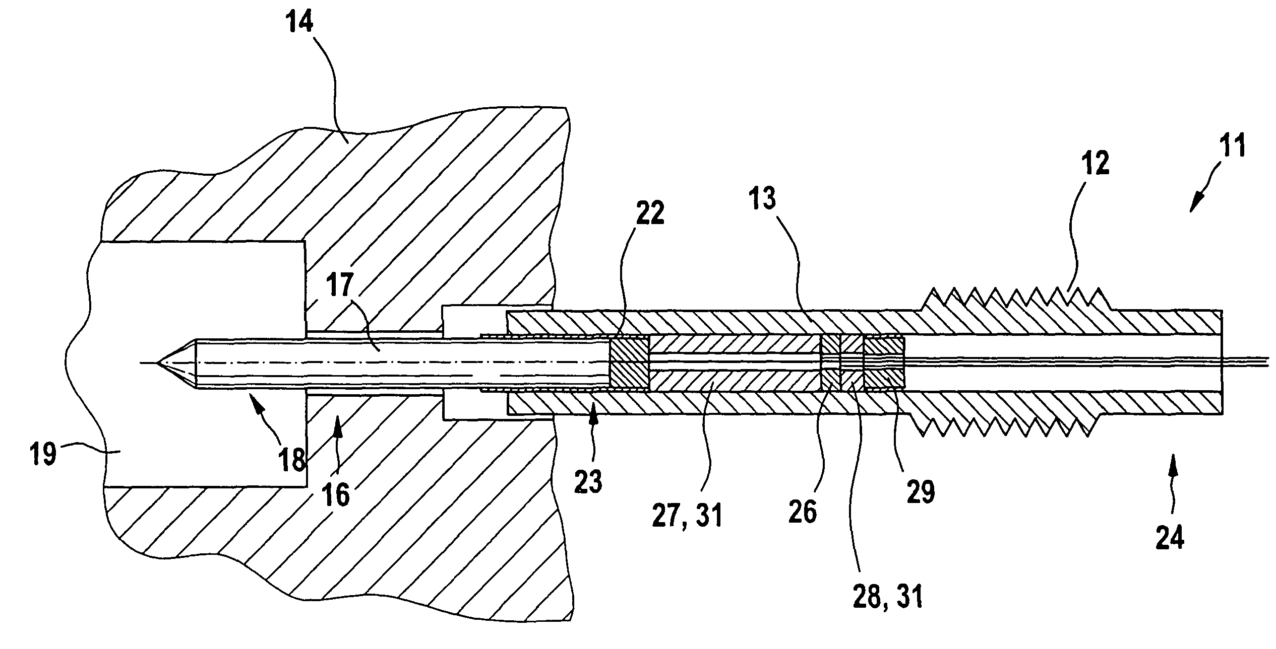
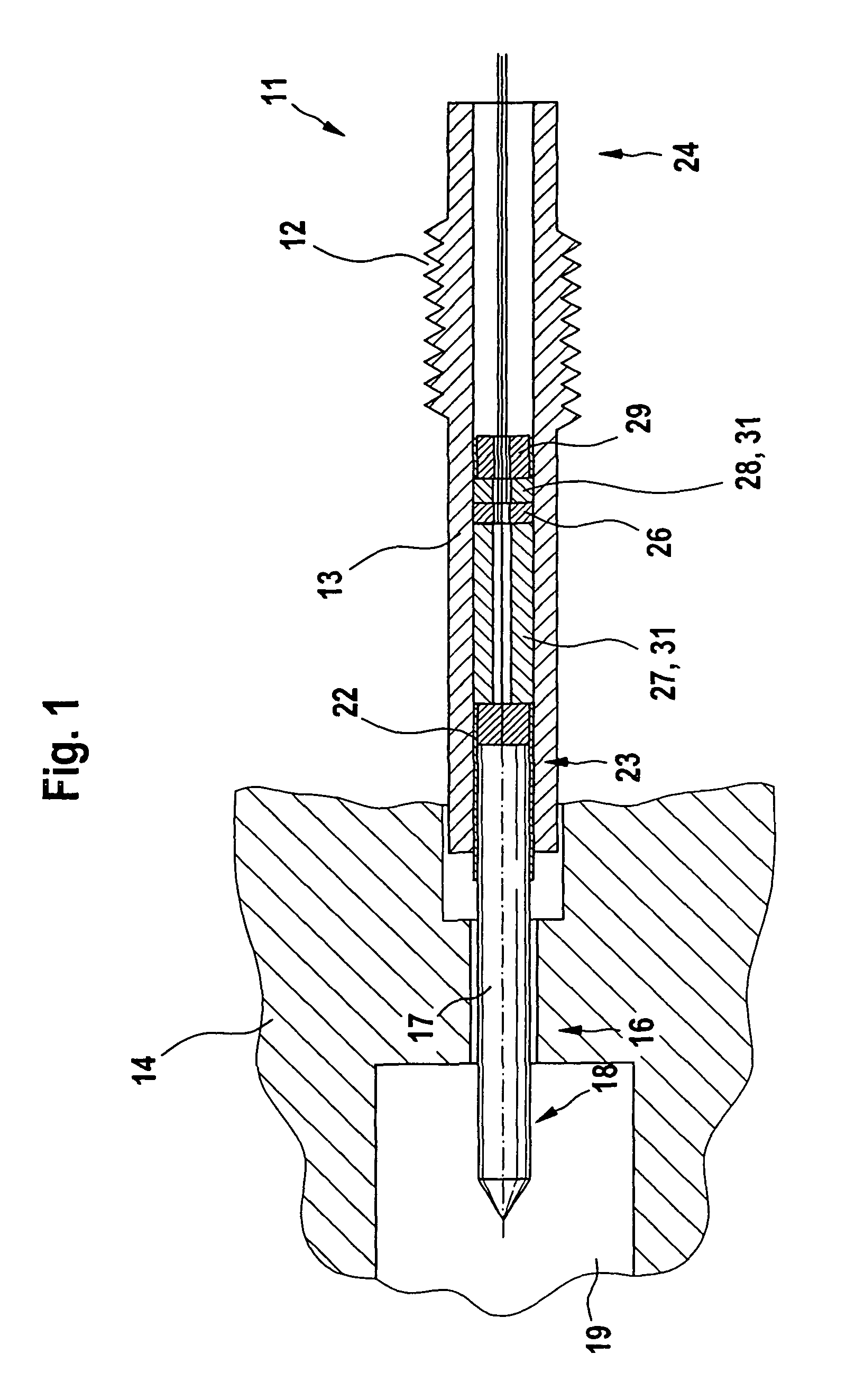
[0011]A device for detecting the combustion-chamber pressure in an internal combustion engine according to FIG. 1 includes a glow plug 11, which is installed in a cylinder head 14 (not shown further) of the internal combustion engine, in particular a diesel engine, with the aid of an external thread 12 of a tubular housing 13 made of metal.

[0012]At a first end 16, glow plug 11 has a heating pin 17, which partially projects from housing 13 and, via a free end 18, projects into an interior chamber 19, forming a combustion chamber, of the internal combustion engine. Heating pin 17 is fixed in place inside glow plug 11 by a fixation member 22. This fixation member 22 is in the form of a support tube, which, in an end region 23 of the other end of heating pin 17, tightly encloses it peripherally, fixation member 22 slightly projecting beyond the other end of heating pin 17. Fixation element 22 in turn is pressed into housing 13.

[0013]As an alternative, fixation member 22 could also be re...


PUM

PropertyMeasurementUnit
combustion-chamber aaaaaaaaaa
pressureaaaaaaaaaa
forceaaaaaaaaaa

Abstract

A device for detecting the combustion-chamber pressure in an internal combustion engine is configured in such a way that the combustion-chamber pressure is able to be detected in a reliable and reproducible manner. To this end, a heating pin exposed to the combustion-chamber pressure is fixed in place in a housing of the glow plug with the aid of a fixation member. A sensor is affixed in the housing of the glow plug via a fixation element set apart from this fixation member. This sensor detects the elastic longitudinal expansion of the housing caused by the combustion-chamber pressure between the end of the fixation member facing the sensor and the fixation point of the fixation element on the housing. This device is preferably utilized in the automotive industry.

Description

BACKGROUND INFORMATION[0001]A device for detecting a combustion-chamber pressure in a diesel engine is described in German Patent No. DE 196 80 912, the device having a pressure sensor and a heating section of a glow plug. This heating section faces an interior of a cylinder of the diesel engine and is able to be acted upon by the combustion-chamber pressure. A fixation element fixes the heating section in place inside a housing of the glow plug. The pressure sensor is disposed between this fixation element and the heating section.[0002]In this system the heating section embodied as a heating pin, and the pressure sensor is braced by the same fixation member with respect to the housing of the glow plug, so that the pressure sensor is acted upon by at least approximately the entire force acting on the heating pin. With certain sensor materials this has the disadvantageous result that the pressure sensor is also operated in its non-linear region, which leads to a non-reproducible meas...

Claims


Application Information

Patent Timeline
Patent Type & Authority Patents(United States)
IPC IPC(8): G01M15/08G01L23/22
CPCF23Q2007/002G01L23/10G01L23/222
Inventor LUDWIG, THOMASKERN, CHRISTOPH
Owner ROBERT BOSCH GMBH
Why Eureka
Try Eureka