Locking device

a technology of locking pins and locking pins, which is applied in the direction of screwdrivers, threaded fasteners, manufacturing tools, etc., can solve the problems of inability to withstand a limited torque of locking pins, inconvenient unfastening or rotation of one component, and inability to adjust the position of the locking pin, so as to improve the grip and reduce the cost of machining and production.

Active Publication Date: 2010-06-08
PARKER HANNIFLIN +1
View PDF18 Cites 21 Cited by
  • Summary
  • Abstract
  • Description
  • Claims
  • Application Information

AI Technical Summary

Benefits of technology

[0006]The rotation of any two suitable interconnected components may be prevented by the locking device. For example, the locking device may prevent the rotation of a threaded component such as a bolt head or a nut relative to a body in which or to which it is threaded, a bayonet connection relative to a body in which it is provided or two interconnected components such as nuts, attached to each other by a screw thread or some other mechanism.
[0011]The grooves preferably comprise a V-shaped cross-sectional profile in order to provide improved grip. The grooves may be provided by ridges extending from the surface of the locking plate and the body or medial plate. Alternatively, the grooves may be provided by ridges extending from one surface and indentations provided in the other corresponding surface.
[0012]As the locking plate only needs to be rotated by a relatively small angle to be able to be fitted over the component, with the component engaging portion engaging the component, the grooves need not extend over the whole surface of the locking plate. The grooves can extend over only a portion of the locking plate surface to be able to engage with corresponding grooves on corresponding portions of the other component or the medial plate. The grooves could for example extend in arcs of 90° or less on each side of the locking plate. The grooves on the other component or medial plate could also extend in arcs of 90° or less, or smaller arcs such as 70° or 50°. As the grooves do not have to extend over the whole surface of the locking plate, machining and production costs are reduced. The grooved surface portions of the plates preferably extend at least in the region of the fixing holes and / or slots.

Problems solved by technology

Inappropriate unfastening or rotation of one component, such as a bayonet connection or threaded fastener, relative to another component can be very problematic.
A problem with such a method, is that the locking pins are only able to withstand a limited torque, typically 150 lb.f.ft (200 Nm) before failure.
However, this prevents its future removal.
Furthermore, use of locking pins generally requires the bayonet connection or threaded fastener to be oriented in a particular manner in order to allow the locking pin to be located in the pre-formed socket making it awkward to lock in place.

Method used


Image

  • Locking device
  • Locking device
  • Locking device

Examples


Embodiment Construction

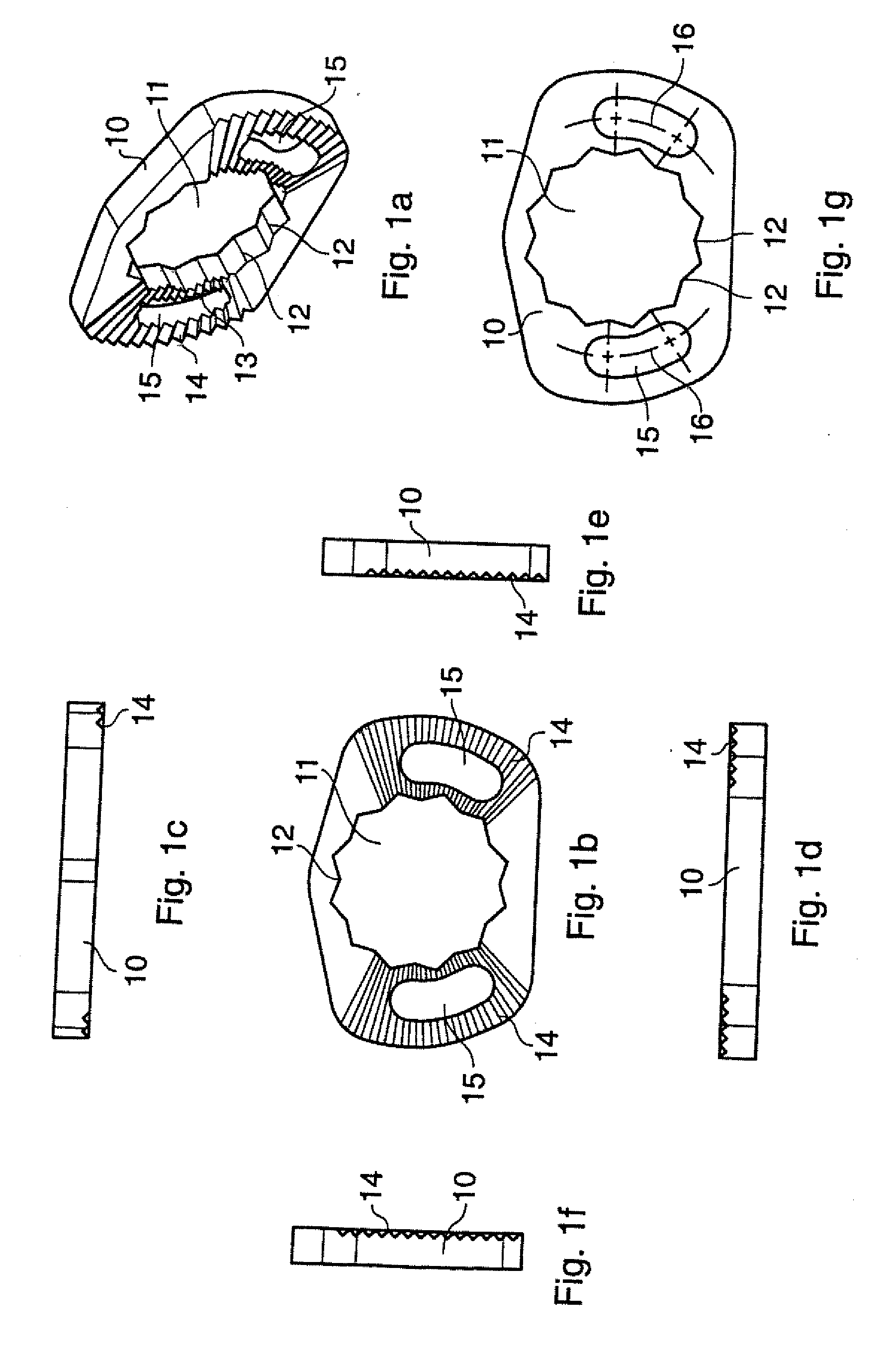
[0027]FIG. 1a shows a perspective view of a locking plate 10. The locking plate 10 has a component engaging portion, in this example a receiving hole 11 to be fitted, in use over a head of a first component (not shown in this FIG.). The receiving hole 11 has a plurality of equiangularly spaced internal corners 12 to engage with the head of the first component. A surface 13 of the locking plate 10 has grooves 14 to engage with a grooved surface carried by another component or to which the first component is connected. Two fixing holes, in this example curved fixing slots 15, are provided for fixing members to be passed through to force the grooves 14 of the locking plate 10 into engagement with a grooved surface carried by another component.

[0028]FIG. 1b shows a top view of the locking plate 10. In this example the shape of the receiving hole 11 is defined by two corresponding regular hexagons superimposed upon one another, with one hexagon being rotated relative to the other by 30°....


PUM

PropertyMeasurementUnit
anglesaaaaaaaaaa
anglesaaaaaaaaaa
center of curvatureaaaaaaaaaa

Abstract

A locking device is disclosed for preventing rotation of one component relative to another component to which it is connected. The locking device comprises a locking plate having a component engaging portion to engage one component, A surface of the locking plate is grooved to engage with a grooved surface carried by the other component. One or more fixing holes are provided for one or more fixing members to be passed through, to force the grooved surface of the locking plate into engagement with the grooved surface carried by the other component.

Description

CROSS REFERENCE TO RELATED APPLICATIONS[0001]This application is a continuation of co-pending International Application No. PCT / GB05 / 001020 filed on Mar. 18, 2005, which designated the United States and is incorporated herein by reference, and which claims priority to Great Britain Patent Application Serial No. 0406879.7 filed on Mar. 26, 2004.BACKGROUND OF THE INVENTION[0002]The present invention relates to locking devices, in particular to a locking device for preventing rotation of one component relative to another component to which it is connected.[0003]Inappropriate unfastening or rotation of one component, such as a bayonet connection or threaded fastener, relative to another component can be very problematic. Many different ways of preventing inappropriate unfastening have been devised, which generally involve use of a locking pin or cam surface to prevent rotation of one component relative to the other. For example, it is common to use one 15 or more locking pins that are i...

Claims


Application Information

Patent Timeline
Patent Type & Authority Patents(United States)
IPC IPC(8): F16B39/10H01J49/38H01J49/40
CPCF16B39/10Y10T403/70Y10T29/49826F16B21/02
Inventor DAVIS, MATHEW
Owner PARKER HANNIFLIN
Why Eureka
Try Eureka