Fuel cell minimum fuel recycle with maximum fuel utilization

a fuel cell and maximum fuel utilization technology, applied in the field of fuel cells, can solve the problems of fuel maldistribution, fuel maldistribution, and the inability to meet the instantaneous load of the fuel cell power plant, and achieve the effect of high fuel utilization, high reliability of the fuel cell power plant, and elimination of stack-to-stack fuel maldistribution

Active Publication Date: 2010-06-08
AUDI AG
View PDF11 Cites 3 Cited by
  • Summary
  • Abstract
  • Description
  • Claims
  • Application Information

AI Technical Summary

Benefits of technology

[0005]Objects of the invention include: eliminating the need of a mechanical fuel recycle gas pump or compressor in fuel cell power plants; providing very high fuel utilization with high reliability in fuel cell power plants; eliminating stack-to-stack fuel maldistribution in fuel cell power plants; reducing the range of performance required of fuel recycle gas impellers; reduced cost fuel cell power plants; and improved fuel cell power plants.
[0006]This invention is predicated primarily on recognition of the fact that the maximum utilization of fuel in a fuel cell stack that can be achieved without localized fuel starvation on the fuel cell anodes is lowest at low power levels; consequently, a fixed or modestly varying amount of recycle fuel flow adequate at low power levels will prevent fuel starvation for all power levels without high recycle fuel flows. This invention is predicated on the realization that an electrochemical hydrogen pump will pump only H2, and no inert gases, and that an ejector may be designed with substantially fixed main and secondary flows.
[0007]According to the present invention, a fuel cell power plant includes (a) a plurality of fuel cell stacks in serial fuel relationship or (b) a single stack; recycle gas from the fuel outlet of the one stack, or from the last stack of the series, is driven to the fuel inlet of one or more stacks by a passive (non-moving) fuel recycle gas pump, such as an ejector or an electrochemical hydrogen pump; recycle fuel flow sufficient to avoid localized fuel starvation at the lowest power level of the fuel cell power plant is maintained with little or no increase at all power levels (recycle fuel flow at full rated load being less than twice the flow at minimum load), so that the passive fuel recycle pump can be designed to operate in a very small range of performance, avoiding high fuel recycle gas flow rates.

Problems solved by technology

Providing exactly the amount of fuel which is required for the instantaneous load on the fuel cell power plant cannot be achieved in fuel cells utilizing current technology due to local fuel starvation at various parts of individual cells and among various cells of a fuel cell stack, which in turn is caused by maldistribution of fuel.
If a multi-pass fuel distribution system is used, in which a portion of all cells receive fuel traveling in one direction through the stack, after which the fuel is turned so that it passes through the other half-portion of all of the cells, variations in leakage at the turn manifold cause maldistribution variations.
In such a case, fuel maldistributions may result from variations in fuel distribution to the respective stacks.
However, the fuel that is recycled typically has to have sufficient pressure to overcome the fuel flow field pressure drop, which requires a pump or compressor of some sort, in the usual case.
These are required to operate at very high speeds (in excess of 20,000 rpm), are noisy and are unreliable.
Other forms of impellers, such as electrochemical hydrogen pumps and ejectors, have heretofore been incapable of use across a wide range of power output operating conditions.

Method used


Image

  • Fuel cell minimum fuel recycle with maximum fuel utilization
  • Fuel cell minimum fuel recycle with maximum fuel utilization
  • Fuel cell minimum fuel recycle with maximum fuel utilization

Examples


Embodiment Construction

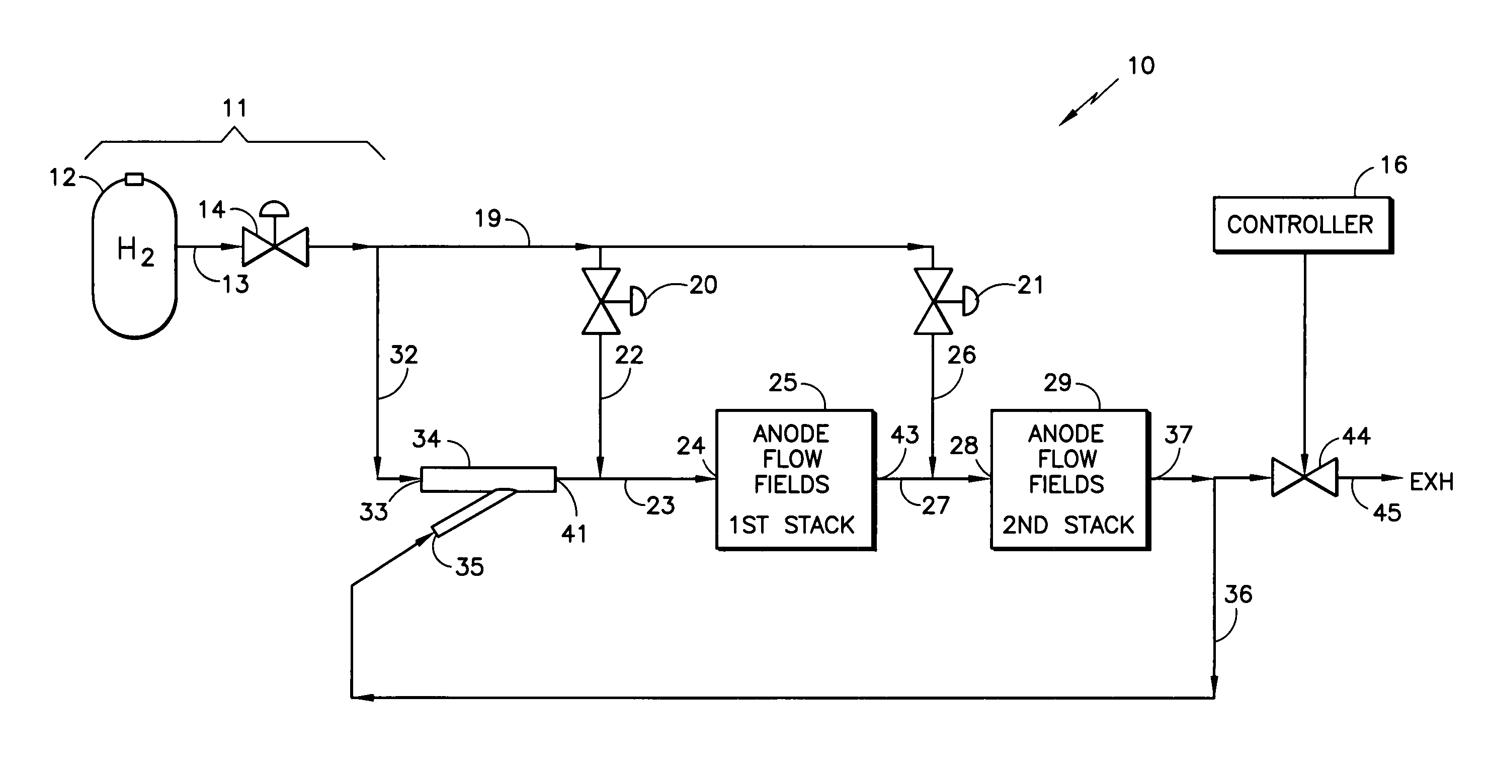
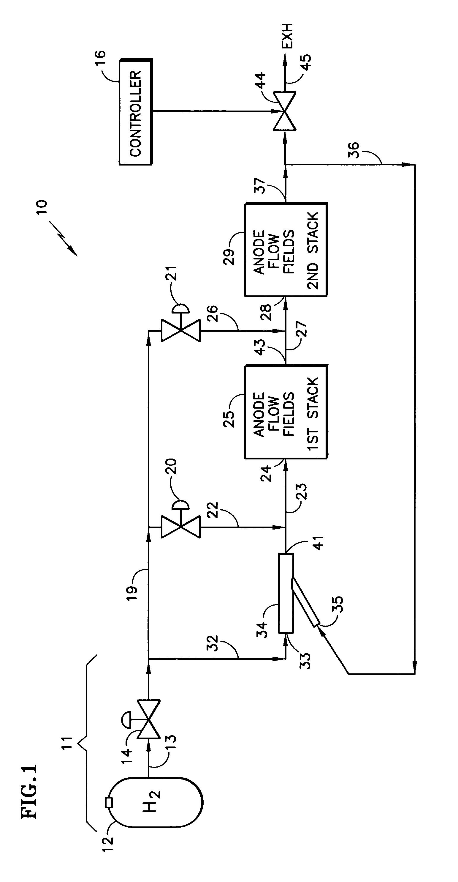
[0019]Referring to FIG. 1, hydrogen is provided to a fuel cell power plant 10, only a portion of which is shown, from a source 11 that receives hydrogen from a supply 12, which may be a conventional reformer or a tank of pressurized hydrogen, and passes it through a conduit 13 to a pressure regulator 14. Fuel is delivered from the source 11 over a conduit 19 to a pair of pressure regulators 20, 21. Fuel from the pressure regulator 20 passes over conduits 22, 23 to an inlet 24 of the anode flow fields of a first fuel cell stack 25. Fuel from the pressure regulator 21 passes through conduits 26, 27 to an inlet 28 of the anode flow fields of a second fuel cell stack 29.

[0020]According to one aspect of the invention, a fixed amount of fuel is brought from the source 11 over a conduit 32 to a primary inlet 33 of an ejector 34, the secondary inlet 35 of which is connected by a conduit 36 to an outlet 37 of the anode flow fields of the second stack 29, to drive fuel recycle gas through the...


PUM

PropertyMeasurementUnit
timeaaaaaaaaaa
poweraaaaaaaaaa
power outputaaaaaaaaaa

Abstract

Recycle fuel gas is provided (36) to an impeller (34, 34a) for application to the input (24) of the anode flow fields of a fuel cell stack (25). The impeller may be an ejector (34) having its primary input (33) connected to a source (11) of hydrogen and its secondary input (35) connected to the outlet (27, 37) of the fuel cells anode flow fields. The ejector outlet provides the minimum fuel flow required at the lowest power rating. The impeller may be an electrochemical hydrogen pump (34a) with a constant current generator (50) providing for a substantially constant recycle flow (the highest not more than double the lowest), and one pressure regulator (20) providing minimum flow of fresh fuel to the fuel inlets of the first stack. Pressure regulators (20, 21) control the amount of fresh fuel to the anode flow fields for power in excess of minimum power.

Description

TECHNICAL FIELD[0001]This invention relates to fuel cells in which the use of a passive fuel recycle impeller, such as an electrochemical hydrogen pump or an ejector, with a fixed, minimum flow of neat fuel from the fuel source, and a substantially uniform amount of fuel recycle gas to the inlet of (a) a first fuel cell stack of a cascaded pair, or (b) a single stack, with neat inlet fuel being provided to one or more fuel cell stacks, bypassing the recycle impeller, as a function of load on the stacks, produces maximum fuel utilization with minimal fuel recycling.BACKGROUND ART[0002]As is known, efficiency of a fuel cell power plant begins with the degree to which all of the fuel provided to the power plant is utilized in production of electricity. This is called overall fuel utilization. It is desirable to achieve fuel utilizations in excess of 98%. Providing exactly the amount of fuel which is required for the instantaneous load on the fuel cell power plant cannot be achieved in ...

Claims


Application Information

Patent Timeline
Patent Type & Authority Patents(United States)
IPC IPC(8): H01M8/04H01M8/24
CPCH01M8/04089H01M8/04097H01M8/04104H01M8/249H01M8/04231Y02T90/32H01M2250/20Y02E60/50H01M8/0681Y02T90/40
Inventor REISER, CARL A.
Owner AUDI AG
Why Eureka
Try Eureka