
Method and receiver for determining a jitter buffer level

a buffer level and receiver technology, applied in the field of data packet reception, can solve the problems of data packet delay, data packet delay, and large delay of data packet transfer by the network, and achieve the effect of minimizing the cost function

Active Publication Date: 2010-06-08
GOOGLE LLC
View PDF11 Cites 9 Cited by
  • Summary
  • Abstract
  • Description
  • Claims
  • Application Information

AI Technical Summary

Benefits of technology

The present invention is about determining a suitable buffer level for a jitter buffer in a receiver. The invention uses statistical measures to collect information about the network conditions and uses this information to update a probability mass function. This function is used to define the expected duration of an empty buffer and the risk of packet loss. By continuously updating the probability mass function, the invention can adapt to changing network conditions and minimize the cost function, which includes buffer delay and the expected duration of an empty buffer. The invention also allows for a trade-off between buffer delay and packet losses by adjusting the weighting factor based on the type of data traffic. The invention can indirectly control the buffer level by modifying the length of the decoded signal sample information. The technical effect of the invention is to provide a more efficient and adaptable jitter buffer for receivers.

Problems solved by technology

In packet switched networks, such as the Internet, data packets transferred by the network are subject to varying delays due to network load when transferring a packet, network path for a transferred packet, and other network conditions.
The varying delay of a data packet is mainly due to the delay inflicted by the packet network and is often referred to as jitter.
This is done by holding the packets in a buffer, thus introducing a delay at the receiver, so that future packets that are subject to larger delays will have arrived before their respective time-of-use.
A long delay of a packet may not only result in that the buffer becomes empty, but also that the buffer may be empty for an unacceptable long time.
If the buffer becomes empty, continued playback of the received signal is no longer possible and the delayed packet will be treated as a lost packet.
However, a high buffer level will introduce a long delay at the receiver which is detrimental in itself for two-way human communication.
There is an inevitable trade-off in jitter buffers between buffer delay on the one hand and packet losses due to late arrivals on the other.
Aiming for a low buffer level, and thus a short delay, results in a larger portion of packets being discarded since they will arrive too late for continuous playback, while a high buffer level and a long delay will be very annoying for two-way human communication.
This total delay is hard to estimate and requires synchronized clocks on transmitting and receiving ends.
In addition to requiring synchronized clocks, this solution suffers from the problem of sample clock drift.

Method used


Image

  • Method and receiver for determining a jitter buffer level
  • Method and receiver for determining a jitter buffer level
  • Method and receiver for determining a jitter buffer level

Examples


Embodiment Construction

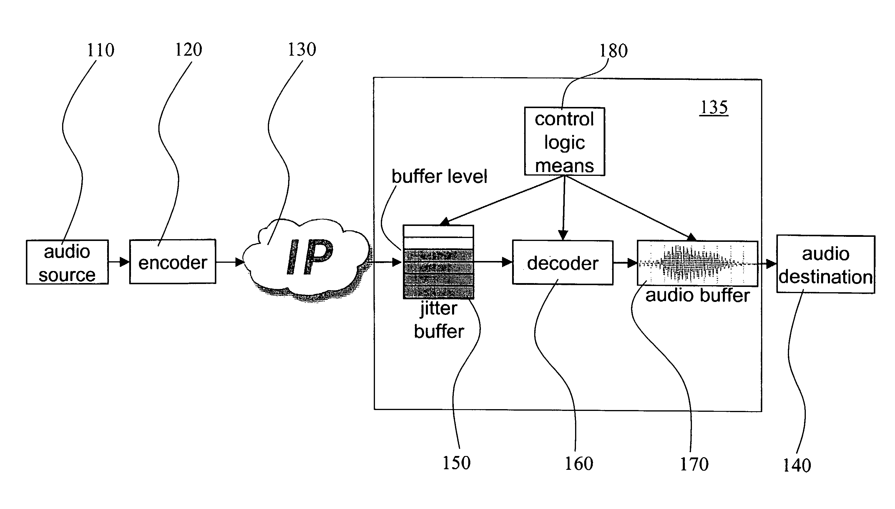
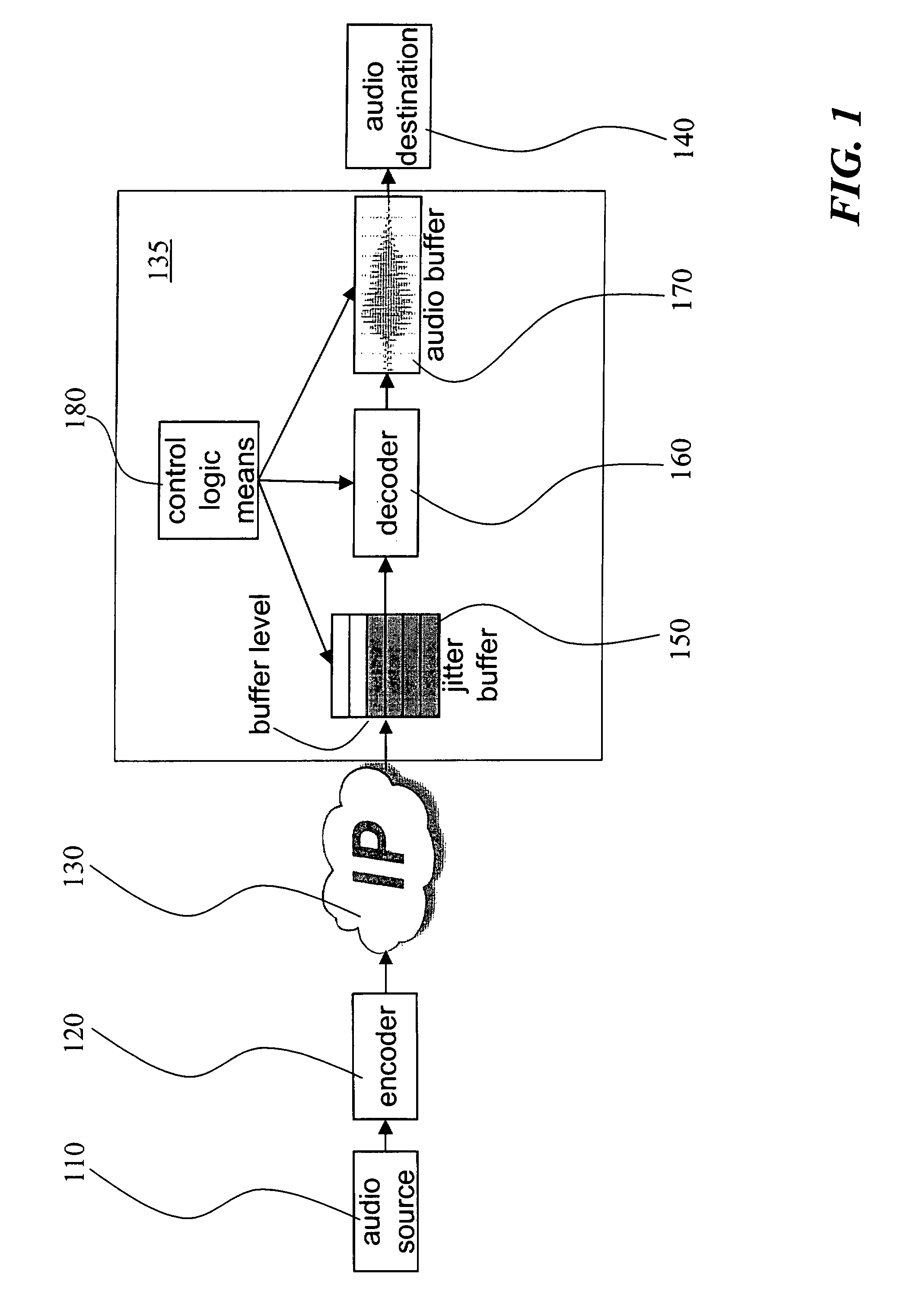
[0018]With reference to FIG. 1, an exemplified system is disclosed in which an embodiment of the inventive receiver is included and configured to operate. The transmitting end includes an audio source 110 and an encoder 120 for encoding and packetizing the audio for transmission as packet data over a packet data network 130, here indicated as an Internet Protocol network. The receiving end includes a receiver 135 and an audio destination 140. The receiver 135 includes a jitter buffer 150, a decoder 160, an audio buffer 170 and control logic means 180. The control logic means 180 exchange signaling information with the jitter buffer and is also responsible for signaling to the decoder 160 and the audio buffer 170. The present invention is concerned with the jitter buffer 150 and the control logic means 180 of the receiver 135. The decoder 160 is at least in part controlled by the control logic means, as will be described below. However, the decoder 160 itself and its operations does ...


PUM


Abstract

The invention relates to a method and a receiver having control logic means for determining a target packet level of a jitter buffer adapted to receive packets with digitized signal samples, which packets are subject to delay jitter, from a packet data network. According to the invention, the jitter buffer is made adaptive to current network conditions, i.e., the nature and magnitude of the jitter observed by the receiver, by collecting statistical measures that describe these conditions. The target buffer level is determined with regard to the effect of packet losses in terms of duration of the discontinued playback of the true signal. This effect is derived from statistical measures of the network conditions as perceived by the receiving side and as reflected by a probability mass function which is continuously updated with packet inter-arrival times. The target buffer level is the result of minimization of a cost function which weights the internal buffer delay and an expected length of buffer underflow.

Description

TECHNICAL FIELD OF THE INVENTION[0001]The present invention generally relates to reception of data packets with digitized signal samples from a packet data network, and more specifically to determining a target packet level of a jitter buffer adapted to receive packets with delay jitter from the network.BACKGROUND OF THE INVENTION[0002]In packet switched networks, such as the Internet, data packets transferred by the network are subject to varying delays due to network load when transferring a packet, network path for a transferred packet, and other network conditions. Thus, data packets that are produced by a transmitter at a constant rate arrive at a receiver with variable delays. The varying delay of a data packet is mainly due to the delay inflicted by the packet network and is often referred to as jitter. The severity of the jitter can vary significantly depending on network type and current conditions; the variance of the packet delay can change with several orders of magnitud...

Claims


Application Information

Patent Timeline
Patent Type & Authority Patents(United States)
IPC IPC(8): H04L12/28
CPCH04J3/0632H04L12/6418H04L12/64H04L65/80
Inventor LUNDIN, HENRIK FAHLBERG
Owner GOOGLE LLC
Learn More